Eureka AIR delivers breakthrough ideas for toughest innovation challenges, trusted by R&D personnel around the world.

Flue gas flow equalizing partitioning device of wet-process desulphurization absorption tower

A wet desulfurization and absorption tower technology, which is applied in gas treatment, separation methods, dispersed particle separation, etc. consumption and other issues

Inactive Publication Date: 2016-08-03
ZHEJIANG TIANDI ENVIRONMENTAL PROTECTION TECH CO LTD
View PDF1 Cites 7 Cited by
  • Summary
  • Abstract
  • Description
  • Claims
  • Application Information

AI Technical Summary

Problems solved by technology

The poor uniformity of the flue gas flow field seriously affects the contact and mass transfer effect between the flue gas and the spray liquid, resulting in low desulfurization efficiency of the absorption tower
In order to improve the desulfurization efficiency, it is necessary to increase the slurry circulation to increase the liquid-gas ratio, which greatly increases the energy consumption of the desulfurization system

Method used


Image

  • Flue gas flow equalizing partitioning device of wet-process desulphurization absorption tower
  • Flue gas flow equalizing partitioning device of wet-process desulphurization absorption tower
  • Flue gas flow equalizing partitioning device of wet-process desulphurization absorption tower

Examples


Embodiment Construction

[0021] The present invention will be further described below in conjunction with the examples. The description of the following examples is provided only to aid the understanding of the present invention. It should be pointed out that for those skilled in the art, without departing from the principles of the present invention, some improvements and modifications can be made to the present invention, and these improvements and modifications also fall within the protection scope of the claims of the present invention.

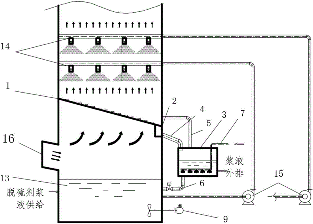
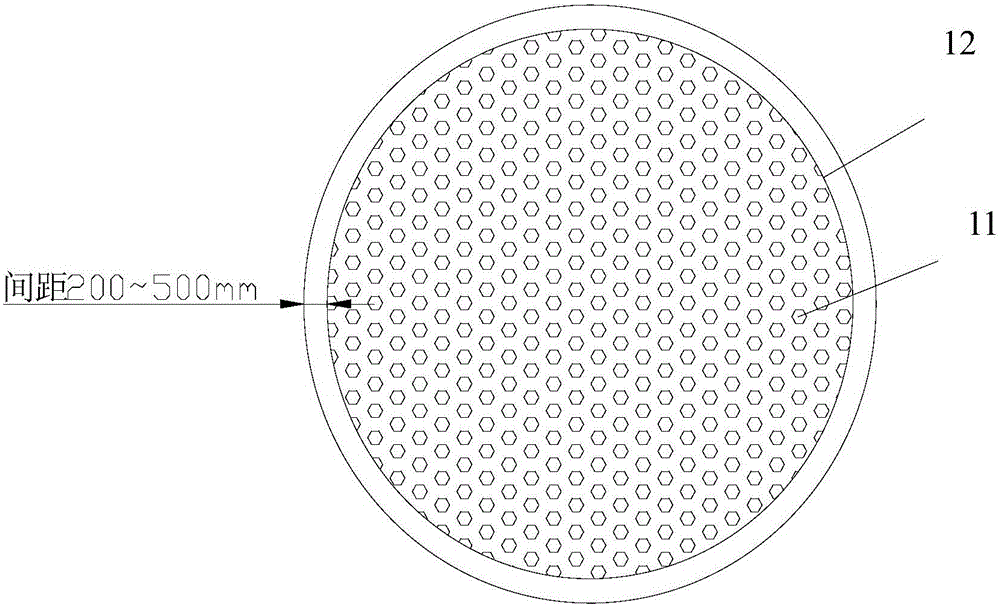
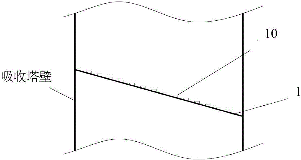
[0022] Such as Figure 1 to Figure 4 As shown, this horizontal wet desulfurization absorption tower flue gas uniform flow partition device includes a uniform flow plate 1, a liquid collection tank 2, an oxidizer 3, a liquid collection pipe 4, a communication pipe 5 and a return pipe 6; The flow plate 1 is arranged between the entrance of the absorption tower and the spray layer 14 on the upper part of the absorption tower. The flow uniformity plate 1 is at a cer...


PUM


Abstract

The invention discloses a flue gas flow equalizing partitioning device of a horizontal wet-process desulphurization absorption tower. The flue gas flow equalizing partitioning device comprises a flow equalizing plate, a liquid collection groove, an oxidizer, a liquid collection pipe, a communication pipe and a reflowing pipe, wherein the flow equalizing plate is distributed between an inlet of the absorption tower and an absorption tower spraying layer at the upper part of the absorption tower; a certain angle is formed between the flow equalizing plate and the horizontal plane; the liquid collection groove is formed in the position of the bottom end of the flow equalizing plate; one end of the liquid collection pipe is connected with the bottom of the liquid collection groove and the other end of the liquid collection pipe is connected with the upper part of the oxidizer; one end of the communication pipe is connected with the top of the oxidizer and the other end of the communication pipe is connected with the upper part of the flow equalizing plate; one end of the reflowing pipe is connected with the bottom of the oxidizer and the other end of the reflowing pipe is connected with the upper part of an absorption tower circulating slurry tank; and an oxidation air pipe is inserted into the liquid level of slurry in the oxidizer, and the tail end of the oxidation air pipe is with an oxidization air distribution pipe with a plurality of small branch pipes. The flue gas flow equalizing partitioning device has the beneficial effects that the distribution of a flue gas flow field in the absorption tower can be improved, and the slurry in the absorption tower can be controlled by partitions according to the pH value, so that the oxidization efficiency and the absorption efficiency are effectively improved and the performance of a whole desulphurization system is improved.

Description

technical field [0001] The patent of the present invention relates to a flue gas uniform flow partition device, in particular to a flue gas uniform flow partition device for a wet desulfurization absorption tower. Background technique [0002] At present, most of the wet desulfurization absorption towers adopt the empty tower spray structure. After research and analysis of the flue gas flow field in the tower, it is found that the distribution of the flue gas flow field between the absorption tower entrance and the first spray layer is very uniform. Difference. In any cross-section between the top of the absorption tower inlet flue and the upper first spray layer, the flue gas velocity away from the flue gas absorption tower entrance is relatively high, while the flue gas velocity close to the absorption tower entrance is relatively low. The poor uniformity of the flue gas flow field seriously affects the contact and mass transfer effect between the flue gas and the spray l...

Claims


Application Information

Patent Timeline
Patent Type & Authority Applications(China)
IPC IPC(8): B01D53/18
CPCB01D53/18B01D2257/302
Inventor 徐灏王汝能戴逸明廖达琛沈海涛刘海蛟李清毅陈瑶姬
Owner ZHEJIANG TIANDI ENVIRONMENTAL PROTECTION TECH CO LTD
Why Eureka
Eureka Blog
Learn More