Die ejection rod structure and ejection rod installation method

A die ejector and ejector technology, applied in the field of stamping dies, can solve the problems that ejector pins cannot be used universally, ejector pin positions cannot be adjusted, etc., and achieve the effects of improving installation efficiency and installation quality, convenient and quick installation, and convenient disassembly and assembly.

Inactive Publication Date: 2016-08-03
ZHEJIANG GEELY AUTOMOBILE +2
View PDF7 Cites 2 Cited by
  • Summary
  • Abstract
  • Description
  • Claims
  • Application Information

AI Technical Summary

Problems solved by technology

[0003] The purpose of the present invention is to overcome the disadvantage that the ejector pin position cannot be adjusted in the current mold ejector pin structure, and the ejector pin cannot be used for different large-scale stamping dies, and to provide a position-adjustable ejector pin for different large-scale stamping dies. Mold ejector pin structure and ejector pin installation method that can be used universally in the mold

Method used


Image

  • Die ejection rod structure and ejection rod installation method
  • Die ejection rod structure and ejection rod installation method
  • Die ejection rod structure and ejection rod installation method

Examples


Embodiment Construction

[0015] The present invention will be further described below with reference to the drawings.

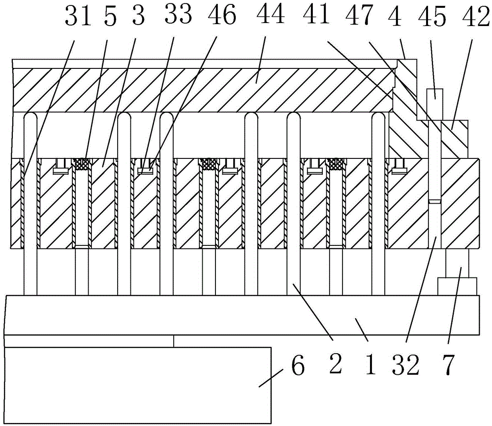
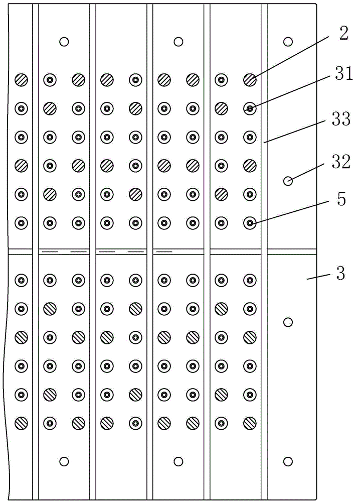
[0016] As attached figure 1 , Attached figure 2 , Attached image 3 Shown: a mold ejector rod structure, including: a workbench 3, a pallet 1 located on the lower side of the workbench 3, an ejector rod group composed of multiple ejector pins 2, a pallet lifting device, and a lower mold 4; The upper end of the worktable 3 is provided with twelve rows of guide holes 31 penetrating the lower end of the worktable 3 and having a diameter clearance fit with the diameter of the mandrel 2; the lower mold 4 includes: a lower mold with sliding holes 41 penetrating the upper and lower ends The seat 42, the side wall is in clearance fit with the sliding hole 41 and the lower mold core 44 is located in the sliding hole 41, two positioning pins 45 and twenty T-shaped screws 46 and twenty nuts (not shown in the drawings); The lower mold base 42 is detachably connected to the upper end of the workta...


PUM


Abstract

The invention relates to the field of stamping dies, and aims to provide a die ejector pin structure and an ejector pin installation method. A mold ejector structure, comprising: a workbench, a supporting plate located at the lower side of the workbench, a ejector group consisting of a plurality of ejector pins, a lifting device for the supporting plate, and a lower die; the upper end of the workbench is provided with: Several rows of guide holes that penetrate the lower end of the worktable and match the diameter of the mandrel; the lower mold includes: a lower mold base with sliding holes passing through the upper and lower ends; The mold core; the lower mold base is detachably connected to the upper end of the worktable; the supporting plate supports the lower end of the ejector rod; the upper end of each ejector rod passes through a guide hole and extends into the sliding hole. The ejector pin structure of the mold can be adjusted according to the needs of processing workpieces, and the ejector pins can be used in common for different large stamping dies.

Description

Technical field [0001] The invention relates to the field of stamping molds, in particular to a mold ejector rod structure and an ejector rod installation method. Background technique [0002] The stamping die has an ejector rod for ejecting the workpiece; the utility model of Chinese Patent Application No. CN201220346913.5 discloses a new type of steel plate die ejector rod structure, including a lower template, which is provided with a guide hole, and the mold ejector rod penetrates Through the guide hole, the end of the mold ejector rod is fixedly connected to the ejector rod support plate. When working, the press ejector rod of the press can be completed by acting on the ejector rod support plate. There is no need to pay attention to the position of the press ejector rod, which can reduce the pressure. The time for placing and centering the ejector rod of the machine is easy to operate, has the advantages of simple manufacturing process and good balance of the ejector rod of ...

Claims


Application Information

Patent Timeline
IPC IPC(8): B21D37/10B21D45/04
CPCB21D37/10B21D45/003B21D45/04
Inventor 李林峰章丽萍
Owner ZHEJIANG GEELY AUTOMOBILE
Why Eureka
Try Eureka