Device for drying sludge with bottom air admission structure

A technology of sludge drying and sludge, which is applied in the direction of sludge treatment through temperature control, dehydration/drying/concentrated sludge treatment, etc., can solve the problems of uneven drying degree, achieve improved drying efficiency, low energy consumption, The effect of improving porosity and fluidity

Pending Publication Date: 2016-08-03
广州正晟科技有限公司
View PDF5 Cites 2 Cited by
  • Summary
  • Abstract
  • Description
  • Claims
  • Application Information

AI Technical Summary

Problems solved by technology

In the sludge drying device of the present invention, since the turning device in the drying chamber turns the sludge, the blades or ratchets on the turning assembly that rotates around the rotating shaft cut and break the sludge, which improves the sludge efficiency. The frequency of contact between mud and drying gas can be improved, thus solving the problem of uneven drying degree of the inner and outer parts of the sludge during the drying process

Method used


Image

  • Device for drying sludge with bottom air admission structure
  • Device for drying sludge with bottom air admission structure
  • Device for drying sludge with bottom air admission structure

Examples


Embodiment Construction

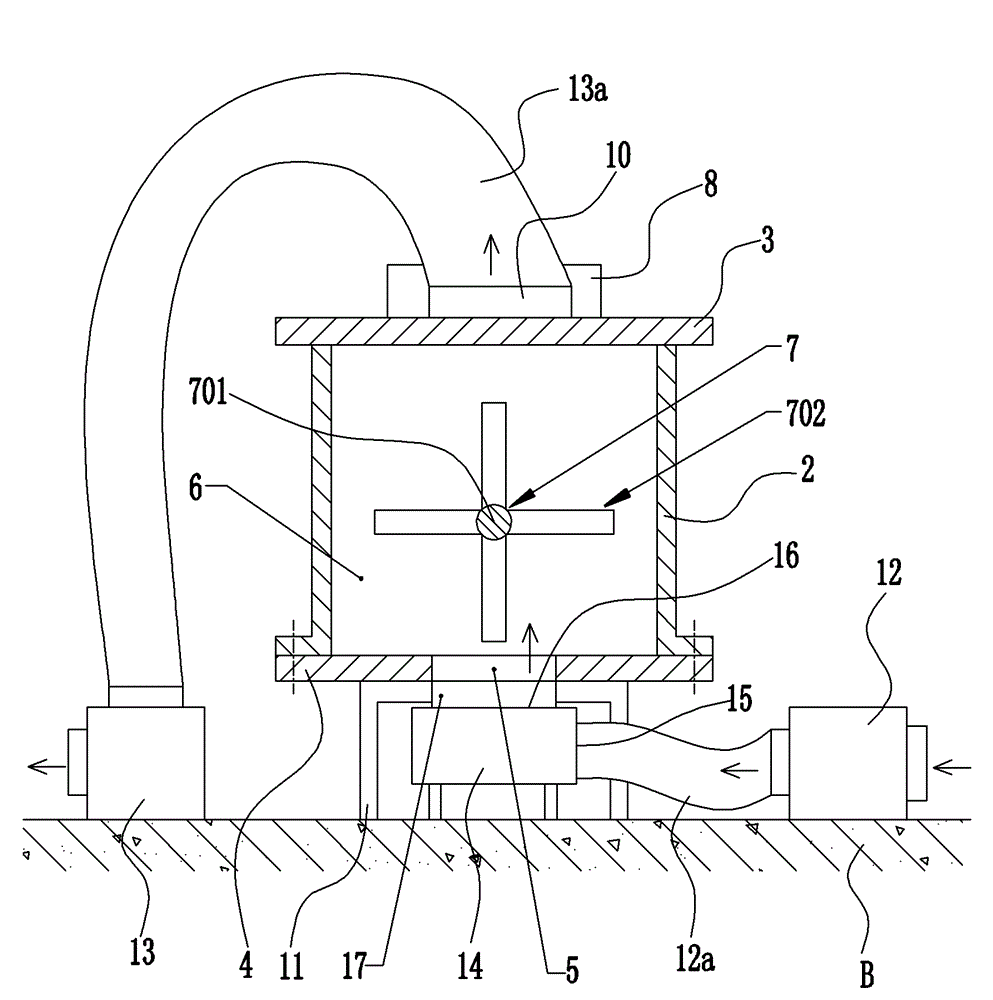
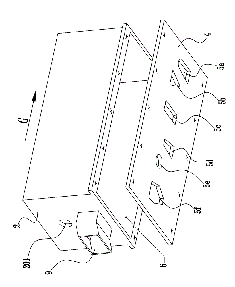
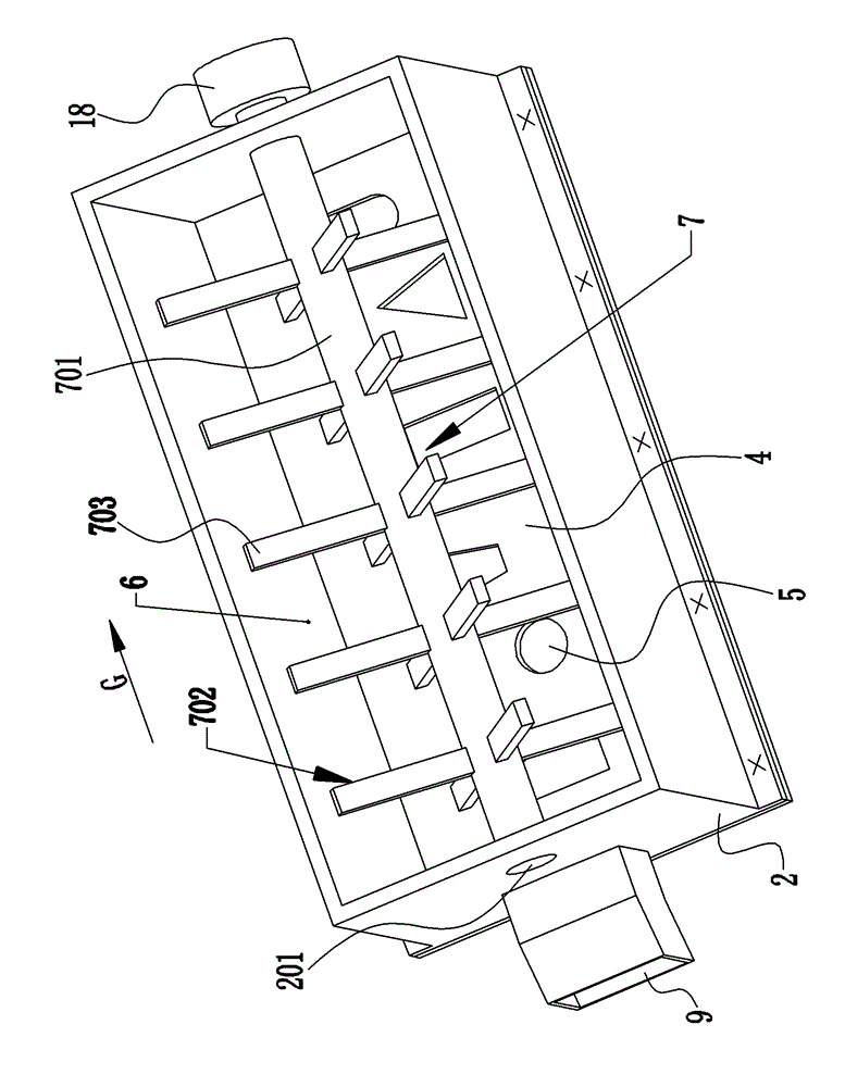
[0021] figure 1 and 2 A preferred embodiment of the sludge drying device with bottom air intake according to the present invention is shown, wherein the structure of the device is schematically represented by a longitudinal partial section view and a transverse section view respectively. As shown in the figure, the bottom air inlet sludge drying device 1 generally has a housing (or casing), a turning device 7 and a supporting device 11 . The casing includes a body 2 , an upper cover (or cover) 3 and a bottom plate 4 arranged on the body 2 . The main body 2, the upper cover 3 and the bottom plate 4 together form a drying chamber 6 with a certain inner space. The turning device 7 is arranged in the drying chamber 6 and is used for shearing, crushing and turning the sludge piled on the bottom plate 4 . The supporting means 11 raises the housing a certain distance h from the ground or floor B. As shown in FIG.

[0022] As shown in the figure, the upper cover 3 of the housing i...


PUM


Abstract

The invention provides a device for drying sludge with a bottom air admission structure. The device comprises a casing, wherein, a drying chamber used for drying the sludge is formed by a space in the casing. A stirring device used for stirring the sludge is arranged in the drying chamber, wherein, the stirring device comprises a rotation shaft and a stirring component fixed on the rotation shaft. A feed inlet used for the to-be-dried sludge and an air outlet used for discharging the dried gas after the sludge is dried are arranged on the upper part of the drying chamber, and a discharge hatch used for the dried sludge is arranged on the circumferential wall of the drying chamber. A communication port is formed on a base plate of the casing, so that the dried gas outside the casing can be introduced into the drying chamber. A support apparatus is provided for supporting the casing, the base plate departs from the ground with a certain distance by the support apparatus, so that the casing and the base plate have a certain space. The invention also provides a method for drying the sludge by using the sludge drying device.

Description

technical field [0001] The present invention relates to the field of sludge drying, and generally relates to a sludge drying device, in particular, to a sludge drying device with bottom air intake in the form of a single unit and the sludge drying device using the sludge drying device Methods of drying sludge. Background technique [0002] With the continuous development of urbanization, the amount of sewage produced in industrial production and life that needs to be treated will gradually increase, and as a by-product of sewage treatment-the output of sludge will also increase. However, compared with sewage , sludge treatment is more difficult. At present, sewage plants generally use the method of concentration and dehydration to pre-treat the sludge in order to reduce the moisture content of the sludge from more than 90% to 60-80%, and the pre-treated sludge is usually landfilled and solidified and drying treatment. Landfill is a relatively simple treatment method. Howe...

Claims


Application Information

Patent Timeline
Patent Type & Authority Applications(China)
IPC IPC(8): C02F11/12C02F11/18
Inventor 谭玮
Owner 广州正晟科技有限公司
Why Eureka
Try Eureka