Multi-cavity steel pipe and concrete combined column and steel beam U-shaped connecting joint and assembling method

A technology of steel pipe concrete and composite columns, which is applied in the direction of construction and building construction, and can solve the problems of simple mechanical properties of joints, incompatibility of economy, affecting the appearance and use of buildings, hindering concrete pouring in pipes, etc., to achieve force transmission Unique method, reasonable stress, and the effect of reducing welding workload

Active Publication Date: 2016-08-03
XI'AN UNIVERSITY OF ARCHITECTURE AND TECHNOLOGY
View PDF8 Cites 3 Cited by
  • Summary
  • Abstract
  • Description
  • Claims
  • Application Information

AI Technical Summary

Problems solved by technology

Because when the side length is small, it is not only difficult to weld, but also hinders the concrete pouring in the pipe. In addition, the beam flange and the inner partition plate penetrate the weld on both sides of the same column wall, and the steel produces a large welding residual stress, which makes the steel at the joint easy to produce delamination or brittle failure
[0005] (2) Affect the appearance and use of buildings
And when applied to corner columns, the horizontal ring plate not only hinders the installation of wall panels, but also causes the reinforcement ring to protrude from the building facade, causing convex corners at the indoor and outdoor joints, which affects the look and feel, which needs to be solved by decoration or ceiling
[0006] (3) The mechanical properties of joints and the simplicity and economy of construction cannot be both
In practical applications, some types of joints have better mechanical properties, and the overall stiffness of the joints is also good, but the amount of materials is large and the construction is complicated

Method used


Image

  • Multi-cavity steel pipe and concrete combined column and steel beam U-shaped connecting joint and assembling method
  • Multi-cavity steel pipe and concrete combined column and steel beam U-shaped connecting joint and assembling method
  • Multi-cavity steel pipe and concrete combined column and steel beam U-shaped connecting joint and assembling method

Examples


Embodiment Construction

[0036] Below in conjunction with accompanying drawing, the embodiment of the present invention is described in detail: present embodiment implements under the premise of the technical scheme of the present invention, has provided detailed implementation mode and concrete operation process, but protection scope of the present invention is not limited to the following the embodiment.

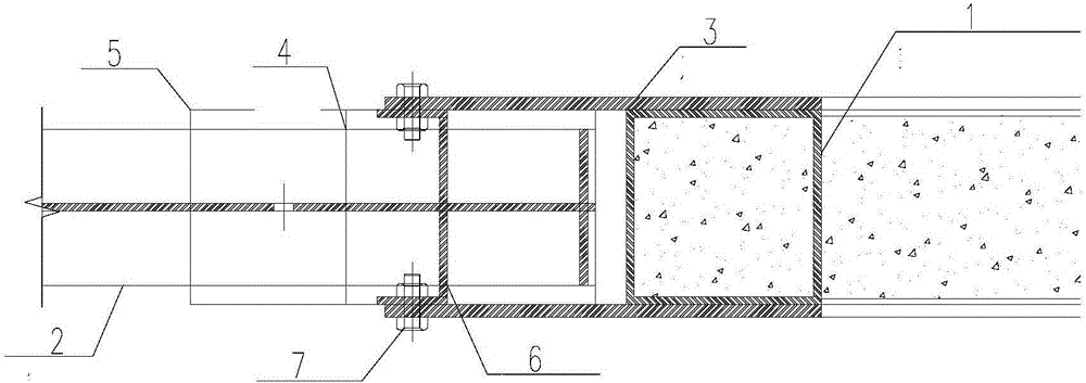
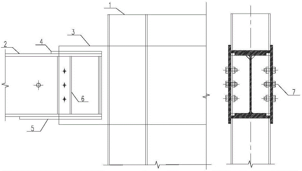
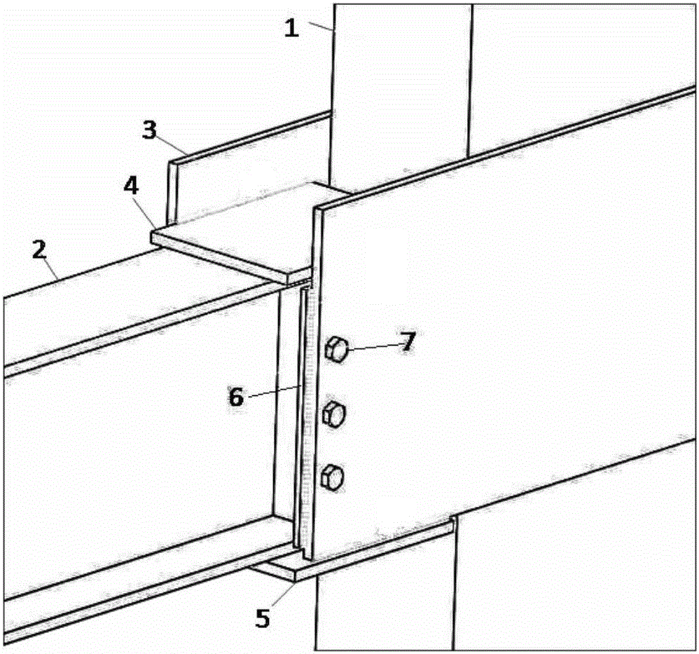
[0037] see figure 1 , figure 2 and image 3 , the present invention includes steel plates 3 arranged on both sides of the multi-cavity concrete-filled steel pipe composite column, that is, two steel plates are arranged on both sides of the multi-cavity steel pipe concrete composite column, and the steel plate 3 is arranged on the multi-cavity steel pipe concrete composite column through the weld seam, and multiple There is also a side base plate 5 between the steel plates 3 on both sides of the cavity concrete-filled steel pipe composite column. Form a U-shaped cavity.

[0038] The upper flan...


PUM


Abstract

The invention relates to a multi-cavity steel pipe and concrete combined column and steel beam U-shaped rigid connecting joint and an assembling method. The multi-cavity steel pipe and concrete combined column and steel beam U-shaped rigid connecting joint comprises steel plates welded to the two sides of a multi-cavity steel pipe and concrete combined column, a side bottom plate is arranged between the steel plates, an upper cover plate is arranged on the upper wing edge of the steel beam, two connecting angles are arranged at a web plate of the steel beam, and the upper cover plate, the side bottom plate and the steel plates are connected. By means of the physical isolation of the beam and the column, the force transmission path of a traditional joint is changed, three-axis stress concentration is eliminated, a plastic hinge can be moved outwards to the beam from the joint, and the defects of tearing damage of the column wing edge of the traditional joint and the dependence of the rotating capability of the joint on the weak plate area of a column web are overcome. The design and principle for a strong column and a weak beam, and a strong joint and a weak component are met. Meanwhile, the joint can be divided into two parts which can be prefabricated in factories respectively, only simple assembling is needed in field installation, and thus the joint is simple in structure and high in assembling degree.

Description

technical field [0001] The invention relates to a multi-cavity steel pipe concrete composite column structure system in the technical field of construction engineering, in particular to a multi-cavity steel pipe concrete composite column and a steel beam U-shaped connection node and an assembly method. Background technique [0002] The multi-cavity concrete-filled steel tube composite column structure system, as a new type of concrete-filled steel tube column structure system, solves the problem of protruding column feet in residential systems. High strength, good plasticity and toughness, convenient construction and so on. [0003] At present, my country's "Technical Regulations for Rectangular Concrete-filled Steel Tube Structures" (GECS159: 2004) provides steel-beam joints for concrete-filled steel tube composite columns, which mainly include inner diaphragm type and outer ring plate type. But so far, there are the following deficiencies in the connection between the ste...

Claims


Application Information

Patent Timeline
Patent Type & Authority Applications(China)
IPC IPC(8): E04B1/30E04B1/58
CPCE04B1/185E04B1/30
Inventor 孙晓岭郝际平薛强樊春雷刘斌陈永昌黄育琪王磊尹伟康何梦楠刘瀚超张峻铭赵子健
Owner XI'AN UNIVERSITY OF ARCHITECTURE AND TECHNOLOGY
Why Eureka
Try Eureka