Inclined trough type 2D electro-hydraulic high-speed switching valve with variable transmission ratio transmission mechanism

A technology of high-speed switching valve and transmission mechanism, which is applied to engine components, valve details, multi-port valves, etc., can solve problems such as damage to the overall structure of the valve body, difficulty in processing the valve core, and reduce the rigidity of the valve core, so as to achieve low processing costs. , Improve reliability and stability, increase the effect of area gradient

Active Publication Date: 2016-08-03
河南航天流体控制技术有限公司
View PDF6 Cites 12 Cited by
  • Summary
  • Abstract
  • Description
  • Claims
  • Application Information

AI Technical Summary

Problems solved by technology

However, it is more difficult to process the spool of this type of valve, and the through hole on the spool has a greater impact on the spool under high pressure and high vibration, which reduces the rigidity of the spool and is easy to break at the through hole; And the plug at the end of the valve core is easy to be washed out when the pressure is too high, causing damage to the overall structure of the valve body
And under high pressure, the "clamping" phenomenon of the valve core will easily cause the flow rate to fail to rise

Method used


Image

  • Inclined trough type 2D electro-hydraulic high-speed switching valve with variable transmission ratio transmission mechanism
  • Inclined trough type 2D electro-hydraulic high-speed switching valve with variable transmission ratio transmission mechanism
  • Inclined trough type 2D electro-hydraulic high-speed switching valve with variable transmission ratio transmission mechanism

Examples


Embodiment Construction

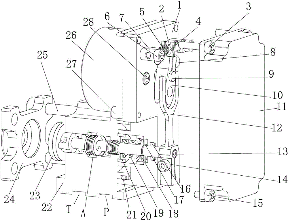
[0042] As shown in the figure, a chute type 2D electro-hydraulic high-speed switching valve with a variable transmission ratio transmission mechanism includes a valve body, a transmission mechanism that drives the valve body to open, and a zero position holding mechanism that drives the valve body to close;

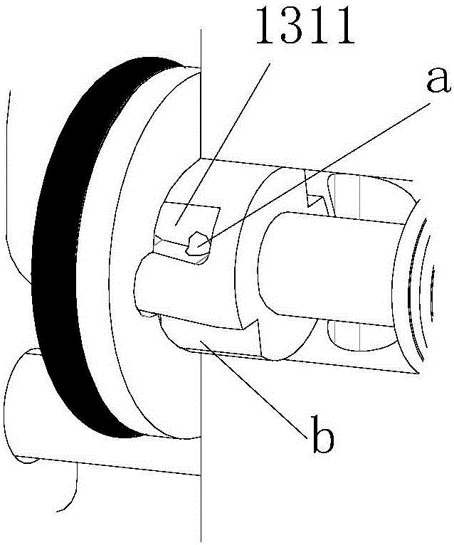
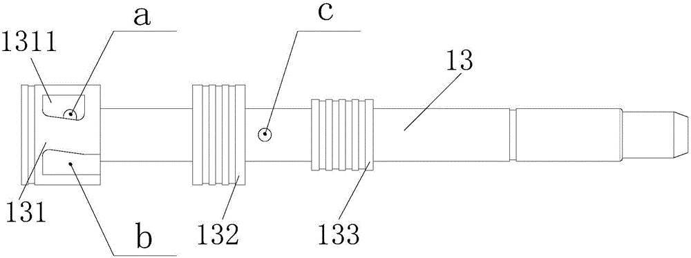
[0043] The valve body includes a servo screw mechanism composed of a valve body 22 and a valve core 13. The valve core 13 is rotatably arranged in the valve body 22. The valve core 13 is sequentially provided with a first shoulder 131 and a second shoulder from left to right. 132 and the third shoulder 133, the left end cap 24 of the valve body 22 and the first shoulder 131 airtightly separate the inner cavity of the valve body 22 into a sensitive cavity f, the first shoulder 131 and the second shoulder 132 separate the valve body The inner cavity of 22 is airtightly partitioned into an annular oil outlet cavity m surrounding the valve core 13, and the second shoulder 132 and...


PUM


Abstract

An inclined trough type 2D electro-hydraulic high-speed switching valve with a variable transmission ratio transmission mechanism comprises a valve body, the transmission mechanism for driving the valve body to be opened and a zero position keeping mechanism for driving the valve body to be closed. An oil inlet cavity communicates with an oil inlet in the valve body and communicates with a valve element through an oil passing hole in the valve element. High-pressure holes communicate with the valve element, and a sensitive cavity communicates with the oil inlet cavity through the oil passing hole, the high-pressure holes and inclined troughs. The sensitive cavity communicates with an oil outlet cavity through low-pressure troughs and the inclined troughs, and the oil outlet cavity communicates with an oil outlet in the valve body. The length, in the axial direction, of a second circular bead is larger than the diameter of the oil outlet, and the oil outlet is located in the motion track of the second circular bead. The lower half part of an upper lifting lever extends into a U-shaped fork of a lower shifting fork, a rotating shaft of rotating equipment is fixedly connected with the upper lifting lever, and a reset spring of the upper lifting lever enables the upper lifting lever to abut against the interior of the lower shifting fork in an inclined manner. The zero position keeping mechanism for forcing the valve body to be kept at the zero position is arranged on the right side of the valve body.

Description

Technical field [0001] The invention relates to an on-off valve, in particular to a chute type 2D electro-hydraulic high-speed on-off valve with a variable transmission ratio transmission mechanism. Background technique [0002] High-speed on-off valves have become an important direction for the development of electro-hydraulic digital control technology, and are widely used in aerospace, hydraulic locking, engineering machinery and military applications. In recent years, as an important part of electro-hydraulic digital control technology, and as a key component to realize electro-hydraulic digital control, high-speed switching valves have put forward higher requirements for them, that is, they must have high pressure resistance, fast response speed, large flow, Good sealing performance and other advantages. [0003] At present, high-speed on-off valves often adopt ball valve, slide valve and poppet valve core structures. The ball valve core has simple structure, good process pe...

Claims


Application Information

Patent Timeline
Patent Type & Authority Applications(China)
IPC IPC(8): F16K11/07F16K31/06F16K31/12F16K31/44
CPCF16K11/07F16K31/0613F16K31/12F16K31/44
Inventor 阮健孙坚刁惠君申屠胜男丁方园孔晨菁孟彬
Owner 河南航天流体控制技术有限公司
Why Eureka
Try Eureka