
A fully premixed condensing heat exchanger

A heat exchanger, fully premixed technology, applied in the direction of heat exchange equipment, heat exchanger type, heat exchanger shell, etc. Heat pipe working life and other issues, to achieve stable work, reduce material consumption, and maintain the effect of heat exchange

Active Publication Date: 2017-08-04
NINGBO HRALE PLATE HEAT EXCHANGER
View PDF5 Cites 0 Cited by
  • Summary
  • Abstract
  • Description
  • Claims
  • Application Information

AI Technical Summary

Problems solved by technology

[0005] The disadvantage of the prior art is that: in order to prevent scale blockage in the heat exchange tube, it must be set to a certain cross-sectional size. In order to meet the needs of heat exchange in a limited space, more heat exchange tubes must be stacked, which compresses the coiled heat exchange tube. The heat flow passes through the gap, and there are a lot of solid particles in the heat flow that will adhere to the surface of the heat exchange tube to form ash blocking, and the adhered dust will further aggravate the process of ash blocking, affecting the pre-designed resistance of the heat exchange tube The balance of the heat exchange tubes will cause the heat exchange tubes to be unable to exchange heat evenly, reducing the heat exchange efficiency of the entire heat exchange tubes, and the solid particles directly adhering to the tube wall are also acidic, which will corrode the heat exchange tubes and affect the heat exchange tube performance. life span

Method used


Image

  • A fully premixed condensing heat exchanger
  • A fully premixed condensing heat exchanger
  • A fully premixed condensing heat exchanger

Examples


Embodiment 1

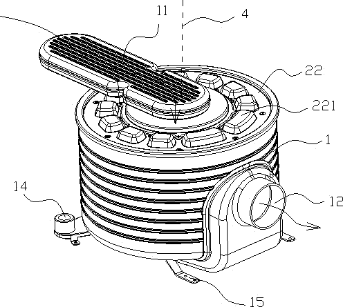
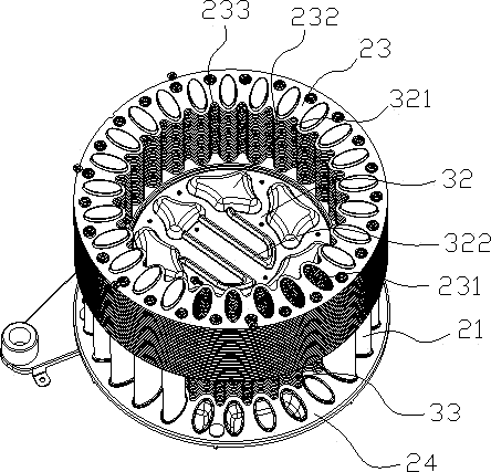
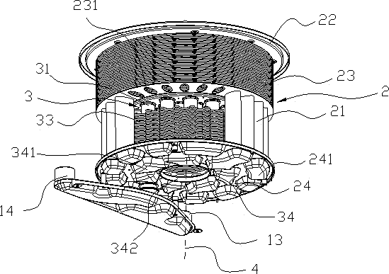
[0031] Such as Figures 1 to 5 As shown, the heat exchanger includes a first heat exchanger 2 and a second heat exchanger 3, and the first heat exchanger 2 is sequentially connected with the second heat exchanger 3 along the axis 4; The heat flow partition divides the cavity of the shell 1 into the main heat exchange chamber and the secondary heat exchange chamber, and the second heat exchanger 3 is arranged in the secondary heat exchange chamber; the first heat exchanger 2 includes the first heat exchange tube group , the first deflector plate and the first fin group; the first heat exchange tube group is composed of a plurality of first heat exchange tubes 21, and the first heat exchange tubes 21 are arranged along the axis 4 and distributed in a ring around the axis 4; The first deflector includes an upper first deflector 22 and a lower first deflector 24, the upper first deflector 22 is arranged in the main heat exchange chamber, and the upper first deflector 22 is arrange...

Embodiment 2

[0039] Such as Figure 6 As shown, the second deflector 32 at the upper end is a plate structure, and the heat flow partition is composed of the second deflector 32 at the upper end, and the second deflector 32 at the upper end is integrated with the first deflector 24 at the lower end Forming (or separately set up and then connected), the inner ring of the first fin group is closed by the integrally formed lower end first deflector 24 and upper end second deflector 32; the heat flow collides with the upper end second deflector When the plate 32 turns to the gap between the first fins 23; at the same time, the heat flow collides with the guide channel provided by the second guide plate 32 at the upper end, and exchanges heat with the water flowing in the guide channel; the second fin The outer ring area of ​​33 is smaller than the area of ​​the first fin 23, and the second fin 33 groups are connected with the first fin 23 in a stepped shape, and the outer ring shape of the sec...

Embodiment 3

[0041] The shape of the outer ring of the second fin 33 is consistent with the shape of the outer ring of the first fin 23, and the second fin 33 is provided with a hole for the first heat exchange tube 21, and the first heat exchange tube 21 passes through the first heat exchange tube 21 The through hole is connected to the second fin 33 to ensure that the second fin 33 has a larger heat exchange area. In some cases, the number of the second fin 33 can be reduced, and the axial height of the entire heat exchanger can be reduced. , providing heat exchange for the first heat exchange tube group 21 at the same time, and reducing the difficulty of mold manufacturing when the first fins 23 and the second fins 33 are stamped and formed.

[0042] The present invention divides the shell into the main heat exchange chamber and the secondary heat exchange chamber, and sets the first fin group in the main heat exchange chamber to ensure sufficient heat exchange between the heat flow and ...


PUM


Abstract

The invention discloses a full-premix condensing heat exchanger which comprises a shell and a heat exchanger, wherein the heat exchanger comprises a first heat exchanger and a second heat exchanger; the first heat exchanger is connected with the second heat exchanger along the axial line; a heat flow partition for partitioning the shell into a primary heat exchange chamber and a secondary heat exchange chamber is further arranged in the shell; the second heat exchanger is arranged in the secondary heat exchange chamber; the first heat exchanger comprises first heat exchange pipes distributed along and around the axial line; the first heat exchange pipes are further connected with first fins; due to gaps between the first fins, a first fin group is formed; heat flow generated by combustion of mixed gas in the inner rings of the first fins is stopped by the heat flow partition and then penetrates through the gaps between the first fins to flow into the secondary heat exchange chamber, to exchange heat with the second heat exchanger. By the arrangement of the first fin group in the primary heat exchange chamber, enough heat exchange areas can be reserved between the heat flow and the first fins as well as between the heat flow and the first heat exchange pipes, and a proper gap is reserved between every two adjacent first fins; the heat exchanger is difficult to block and can difficultly corrode the first heat exchange pipes.

Description

technical field [0001] The invention relates to a heat exchanger, in particular to a fully premixed condensing heat exchanger. Background technique [0002] The existing fully premixed condensing heat exchanger is most commonly used in heat exchange devices such as wall-hung boilers. The flue gas containing heat generated by the combustion of mixed gas passes through the fully premixed condensing heat exchanger, and convectively flows through the fully premixed condensing heat exchanger. The water is preheated, the heat carried by the flue gas is absorbed and condensed, and the heated water flows into the wall-hung boiler to be used by the heat exchanger. [0003] The existing fully premixed condensing heat exchanger includes: an outer shell and ring-shaped heat exchange tubes coiled layer by layer. The heat exchange tube is a flat structure, and the outer shell wraps the heat exchange tube. The mixed gas enters the inner ring of the heat exchange tube from the air inlet an...

Claims


Application Information

Patent Timeline
Patent Type & Authority Patents(China)
IPC IPC(8): F28D7/16F28F1/32F28F19/00F28F9/22
CPCF28D7/1684F28F1/325F28F9/22F28F19/00
Inventor 戴丁军卓宏强孙旭光胡旭
Owner NINGBO HRALE PLATE HEAT EXCHANGER
Learn More