Gear measurement device based on laser displacement sensor and gear measurement method

A laser displacement and gear measurement technology, applied in the direction of measuring devices, optical devices, instruments, etc., can solve the problems of low measurement accuracy and inconvenient measurement, achieve high measurement accuracy, improve measurement accuracy, and simplify the measurement process.

Active Publication Date: 2016-08-03
YANGZHOU UNIV
View PDF8 Cites 60 Cited by
  • Summary
  • Abstract
  • Description
  • Claims
  • Application Information

AI Technical Summary

Problems solved by technology

[0004] Aiming at the problems existing in the existing gear measurement technology, the present invention provides a gear measurement device and a gear measurement method based on a laser

Method used


Image

  • Gear measurement device based on laser displacement sensor and gear measurement method
  • Gear measurement device based on laser displacement sensor and gear measurement method
  • Gear measurement device based on laser displacement sensor and gear measurement method

Examples


Embodiment 1

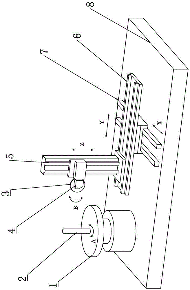
[0024] Such as figure 1 The gear measuring device based on the laser displacement sensor of the present invention includes a worktable 8 on which a workpiece turntable 1 and a three-coordinate translation device with a rotatable measuring head are provided. The workpiece turntable 1 is vertically provided with a mark Zero rotation axis 2, the three-coordinate translation device includes an X-axis guide rail 7 fixed on the worktable 8, a Y-axis guide rail 6 is slid on the X-axis guide rail 7, and a Z-axis guide rail 5 and Z-axis guide are slid on the Y-axis guide rail 6. 5 There is a sliding frame on the sliding frame, and a rotatable laser displacement sensor 4 is arranged on the sliding frame; in order to adjust the angle of laser projection, the sliding frame is equipped with an indexing plate 3, and the laser displacement sensor 3 is set on the indexing plate to follow the points. The dial rotates synchronously; in order to adjust the position of the laser displacement sensor...

Embodiment 2

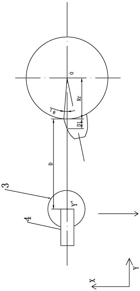
[0027] Such as figure 2 As shown, the method for measuring spur gears or arc gears using the gear measuring device of the present invention is realized by the following steps.

[0028] In the first step, the laser displacement sensor is driven by the servo motor to move along the X-axis and Y-axis rails, and data points on the outer circumference of the zeroing shaft are collected to calibrate the position of the measured gear center axis coordinate system. Specifically, move the laser displacement sensor 4 to the outer circumference of the workpiece turntable 1, rotate the index plate 3 so that the laser beam emitted by the laser displacement sensor 4 is directed horizontally and directly on the circumference of the zeroing axis 2, and then keep the Y and Z guide rails stationary , Move the laser displacement sensor 4 along the X-direction guide 7 to the other side of the circumferential surface at intervals, and collect the interval data points P1, P2, P3...Pn, Pn+1..., when th...

Embodiment 3

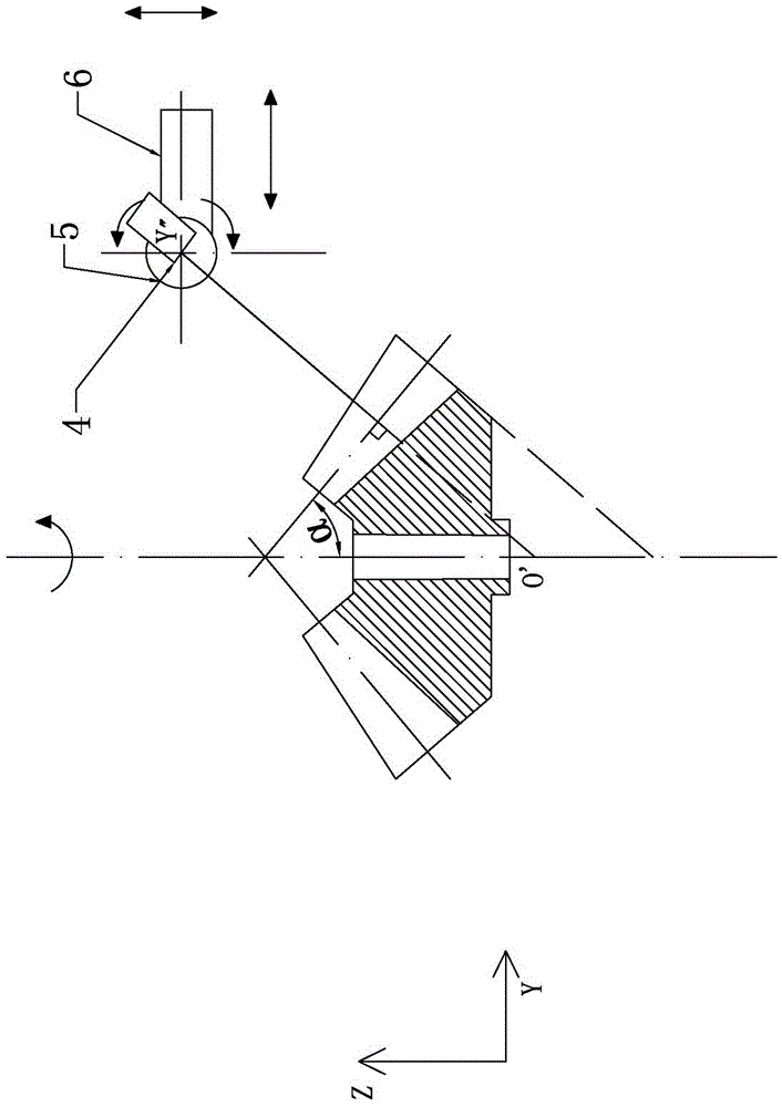
[0033] Such as image 3 As shown, the method for measuring bevel gears by using the gear measuring device of the present invention is realized through the following steps. The difference in Embodiment 2 is embodied in the following steps.

[0034] The second step is to place the measured bevel gear face down on the workpiece turret and adjust it to be coaxial with the zero axis, and move the laser displacement sensor along the Z axis. 0 To be obliquely above the measured gear, the index plate rotates by an angle α, α is the pitch cone angle of the measured bevel gear, adjust along the Y-direction guide so that the laser beam is directly directed on the equivalent tooth profile of the measured gear, and the laser displacement sensor The displacement indication value is zero, then the coordinate of the center point O'of the measured equivalent tooth profile is (X 0 , Y 0 ), the Y of the center point of the laser displacement sensor is marked as Y”. In the third step, the workpiece t...


PUM


Abstract

The invention relates to the technical field of gear measurement and especially relates to a gear measurement device based on a laser displacement sensor and a gear measurement method. The gear measurement device provided by the invention comprises a working table, wherein a work piece revolving table and a three-coordinate horizontal shifting device equipped with a rotatable measurement head are disposed on the working table; a zero marking spindle is disposed vertically on the work piece revolving table; the three-coordinate horizontal shifting device comprises an X-axis guide rail fixed on the working table; a Y-axis guide rail is disposed on the X-axis guide rail in a sliding manner; a Z-axis guide rail is disposed on the Y-axis guide rail in a sliding manner; a slide frame is disposed on the Z-axis guide rail in a sliding manner; and the rotatable laser displacement sensor is disposed on the slide frame. The gear measurement device provided by the invention is characterized in that the laser displacement sensor collects coordinate positions of each measurement point on a measured gear outline. In comparison with contact head measurement based on contact with a work piece, the device and the method provided by the invention have the advantages that measurement accuracy is high; a measurement head motion route does not need to be planned during the measurement; and measurement sources are simplified.

Description

Technical field [0001] The invention relates to the technical field of gear detection of gears, in particular to a gear measuring device and a gear measuring method based on a laser displacement sensor. Background technique [0002] Gear measurement technology can be divided into two categories: contact measurement and non-contact measurement. At present, it is widely used to record the three-dimensional coordinate position of the surface point of the body by contacting the trigger or scanning sensor probe with the surface of the geometric body. Measurement method. This method has slow measurement speed and cumbersome operation. When measuring the gear, the probe touches the surface to be measured, and when the gear rotates, the probe moves along the tooth profile trajectory. This method has the problem of lateral resolution caused by the larger radius of the contact probe, and the movement path of the probe needs to be planned in advance. The widely used contact measurement ca...

Claims


Application Information

Patent Timeline
IPC IPC(8): G01B11/24
CPCG01B11/2416
Inventor 宋爱平邱林沈宇涵彭云
Owner YANGZHOU UNIV
Why Eureka
Try Eureka