
Electronic device and control method thereof

A technology of electronic equipment and control methods, applied in pump control, mechanical equipment, instruments, etc., can solve problems such as large noise, no energy saving, equipment failure, etc., achieve a wide range of applications, save production costs, and achieve the effect of protection

Active Publication Date: 2016-08-03
LENOVO (BEIJING) CO LTD
View PDF10 Cites 12 Cited by
  • Summary
  • Abstract
  • Description
  • Claims
  • Application Information

AI Technical Summary

Problems solved by technology

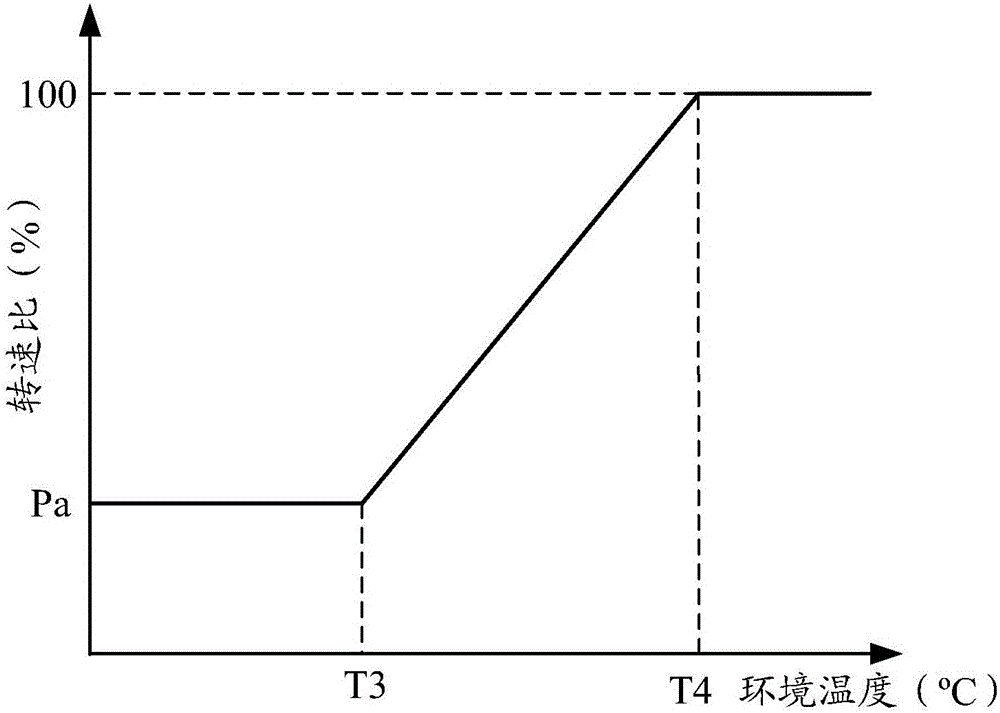
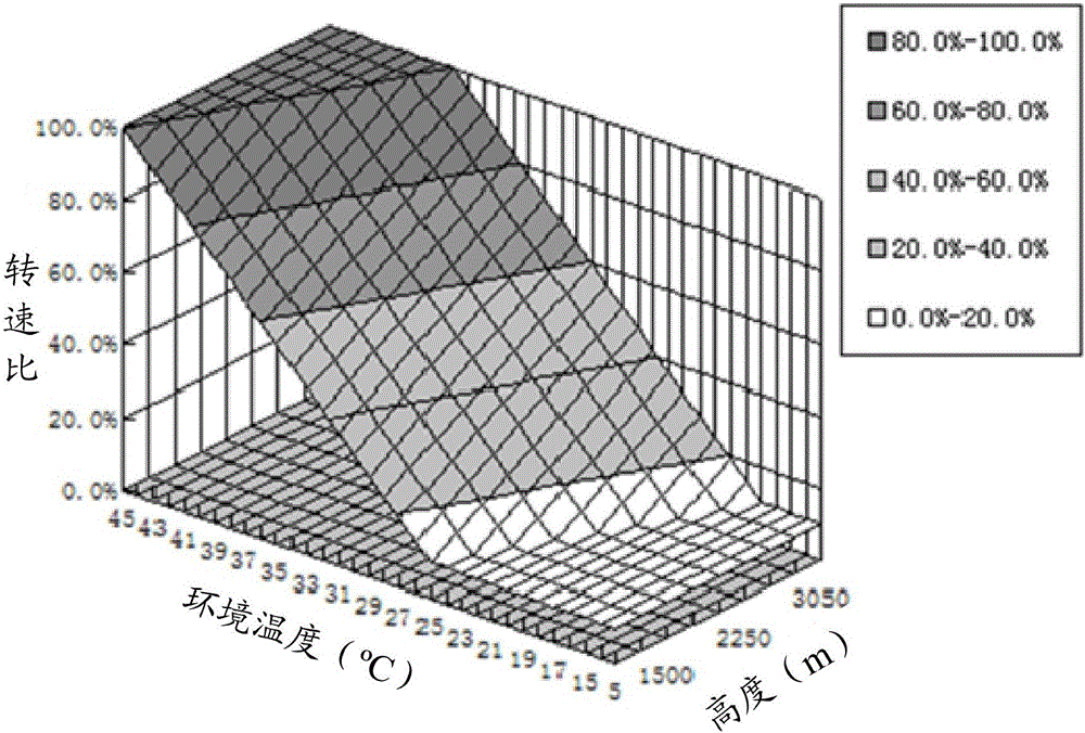
[0002] In the current scheme about the use of fans of electronic equipment, the method of controlling the speed of the cooling fan is only to adjust the speed of the fan according to the temperature of the environment in which the electronic equipment is used. However, for different altitudes, even if the ambient temperature is the same, the difference in atmospheric pressure It will still lead to different air cooling capabilities, so that the adjustment control method of fan speed applicable in low altitude areas may cause the temperature of electronic equipment components in high altitude areas to exceed the standard and cause equipment failure. Therefore, users cannot comprehensively consider electronic equipment. The air pressure changes caused by the different altitudes of the use environment cannot control the fan speed more accurately, which may easily cause damage to the components of electronic equipment
In the existing technical solution, even if the fan speed control that can fully satisfy the high-altitude area can be used, it will generate a lot of noise when used in the low-altitude area, and it is not energy-saving.
In addition, there are currently solutions to use altitude sensors to monitor different altitudes, but such altitude sensors are usually very expensive, which will increase the production cost of the product and reduce the price competitiveness of the product in the market

Method used


Image

  • Electronic device and control method thereof
  • Electronic device and control method thereof
  • Electronic device and control method thereof

Examples


Embodiment Construction

[0020] In order to make the objects, technical solutions and advantages of the present invention more apparent, exemplary embodiments according to the present invention will be described in detail below with reference to the accompanying drawings. Note that in this specification and the drawings, substantially the same steps and elements are denoted by the same reference numerals, and repeated explanation of these steps and elements will be omitted.

[0021] Apparently, the described embodiments are only some embodiments of the present invention, not all embodiments of the present invention. Reference throughout this specification to "one embodiment" or "an embodiment" means that a particular feature, structure, or characteristic described in connection with the embodiment is included in at least one of the described embodiments. Thus, appearances of the phrase "in one embodiment" or "in an embodiment" in the specification are not necessarily all referring to the same embodime...


PUM


Abstract

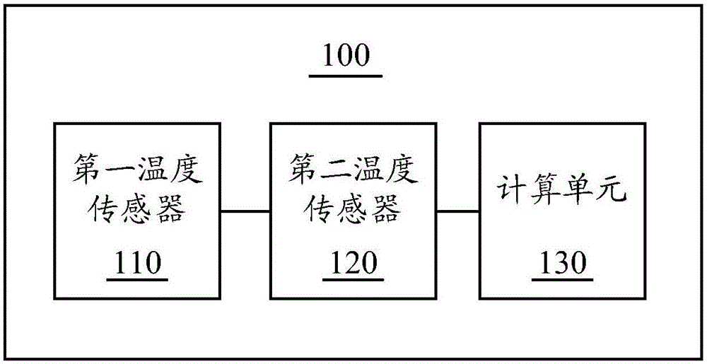
The present invention provides an electronic device. The electronic device comprises a fan for heat radiation and a constant power heat source. The electronic device includes: a first temperature sensor configured to sense the ambient temperature and send the sensed ambient temperature to a calculation unit; a second temperature sensor configured to sense the temperature of the constant power heat source and send the sensed temperature of the constant power heat source to the calculation unit; and the calculation unit configured to calculate the atmospheric pressure at the position where the electronic device is located according to the ambient temperature, the sensed temperature of the constant power heat source and the rotating speed of the fan. The electronic device and the control method thereof are able to perform optimization of the fan application control method of an electronic device in the prior art to allow users to comprehensively take into account the pressure change caused by different altitude height of the application equipment where the electronic device is applied to realize the accurate control of the rotating speed of the fan so as to prevent elements of the device from damaging and realize the protection of the elements of the electronic device.

Description

technical field [0001] The present invention relates to an electronic device, more specifically, to an electronic device and a control method thereof. Background technique [0002] In the current scheme about the use of fans of electronic equipment, the method of controlling the speed of the cooling fan is only to adjust the speed of the fan according to the temperature of the environment in which the electronic equipment is used. However, for different altitudes, even if the ambient temperature is the same, the difference in atmospheric pressure It will still lead to different air cooling capabilities, so that the adjustment control method of fan speed applicable in low altitude areas may cause the temperature of electronic equipment components in high altitude areas to exceed the standard and cause equipment failure. Therefore, users cannot comprehensively consider electronic equipment. The air pressure changes caused by the different altitudes of the use environment canno...

Claims


Application Information

Patent Timeline
IPC IPC(8): H05K7/20
CPCH05K7/20209F04D27/001G01L11/002G01C5/06
Inventor 贺潇
Owner LENOVO (BEIJING) CO LTD
Learn More