
Icebreaker for operation preferably in shallow freezing water

A technology of ice-coated water, icebreaker, applied in the field of shipbuilding

Inactive Publication Date: 2016-08-03
FEDERALNOE GOSUDARSTVENNOE UNITARNOE PREDPRIJATIE KRYLOVSKIJ GOSUDARSTVENNYJ NAUCHNYJ TSENTR
View PDF5 Cites 11 Cited by
  • Summary
  • Abstract
  • Description
  • Claims
  • Application Information

AI Technical Summary

Problems solved by technology

[0007] The proposed invention is aimed at improving the maneuverability of the boat when operating forward and backward in ice as well as in confined environments in open waters, as well as improving its ice walking capability and effectively addressing air ingress between AZT propellers and boat propellers in operation The problem

Method used


Image

  • Icebreaker for operation preferably in shallow freezing water
  • Icebreaker for operation preferably in shallow freezing water
  • Icebreaker for operation preferably in shallow freezing water

Examples


Embodiment Construction

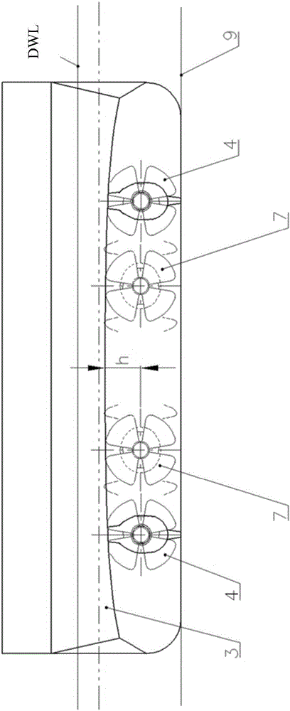
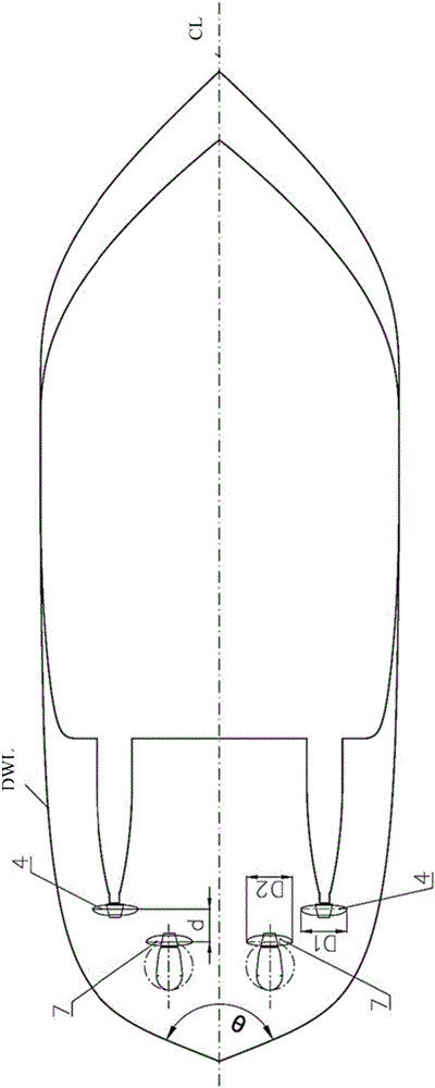
[0020] icebreaker( figure 1 , figure 2 , image 3 ) has a hull 1 with a stern overhang 2 fitted with an ice shield 3 in which the steering / propulsion system is arranged and includes two conventional side boat propellers 4 mounted on shaft 5 and Two 360 degree azimuth propulsion means 6 with propellers 7 mounted on the hull 1 of the ship.

[0021] The stern extension 2 has a wedge shape with a wedge angle θ along the DWL, 90°≤θ≤180°( image 3 ), and this surface is inclined relative to the vertical direction at an angle of α≥30° ( figure 1 ).

[0022] The ice shield 3 has a height at the stern such that the lower edge of the shield 3 is aligned with the axis of rotation of the propeller 7 of the AZT6 ( figure 1 , figure 2 ) between the distance h is not greater than AZT6 ( image 3 ) half of the radius of the propeller 7 (diameter D 2 a quarter of ). In this case, this shroud is arranged to extend beyond the disk of the boat's propeller 4 by a distance L in the bow d...


PUM


Abstract

The invention relates to shipbuilding, and more specifically to the icebreakers and tugboats intended for operation in ice in shallow water conditions. The proposed invention is aimed to improve maneuverability of the ship running both ahead and astern in constrained environment in ice and in open water, as well as to improve its icegoing capabilities and to effectively handle air penetration to the operating AZT propellers and ship propulsors. For this purpose the icebreaker intended for operation preferably in shallow freezing waters comprising a hull with a sled-like stern overhang having flat bottom and ice protection shield along the perimeter of the overhang, and podded propulsion system disposed in the overhang and comprising two side propulsors mounted on the shafts symmetrically to the ship's CL, and arranged with regard to hull height so that the propulsor's tip edges do not protrude beyond the ship's base plane and design waterline at the propellers' location, and, according to the invention, is fitted with two 360-degree azimuth thrusters (AZT) equipped with pulling propellers mounted on the AZT shafts in front of their pods with blade tip edges not protruding beyond the base plane and arranged symmetrically to the ship's CL displaced sternward in such a way that the distance between the disks of AZT propellers and disks of side propulsors is not greater than the diameter of propulsor and the 360-degree turn of azimuth thruster about its axes with no contact to ship's propulsors is provided. In DWL area, the ship's stern overhang is of wedge-type icebreaking shape with 90 DEG-180 DEG wedge angle along the DWL with its surface being inclined at no less than 30 DEG to the vertical. An ice protection shield with wedge-shape cross section does not protrude beyond the ship's hull and is formed so as to extend in the bow direction beyond the disks plane of ship's side propulsors by the value not greater than two diameters of the above-mentioned propulsors; moreover, it has height at which the lower edge of the shield in the stern protrudes upwards from the rotation axes of AZT propellers at least by half the radius of these propellers. The proposed ship intended for operation in shallow freezing water offers improved maneuverability and icegoing capabilities comparing preferably with prototype.

Description

technical field [0001] The present invention relates to shipbuilding, and more particularly to icebreakers and tugboats intended for operation in ice in shallow water situations. Background technique [0002] The main problem of operation in shallow water covered by ice is to provide the ship with a limited draft the effective thrust required to overcome ice resistance, which is the reason for limiting the diameter of the propellers and the power they effectively consume. [0003] Even in the case of deep immersion there is a limit to the power dissipated by a propeller with a certain diameter. This was due to a sudden thrust failure and a significant increase in unstable hydrodynamics and vibrations due to power limitations caused by severe cavitation starting at a fixed propeller diameter. Given the requirement to obtain the highest possible propulsion in order to achieve the highest ice-walking capability, almost every icebreaker is subjected to a first stage of cavitati...

Claims


Application Information

Patent Timeline
IPC IPC(8): B63B35/08B63H5/08
CPCB63B1/08B63B35/08B63B2035/002B63H5/08B63H5/125B63H2005/1254Y02T70/10B63B35/083
Inventor 叶夫根尼·米哈洛维奇·阿波洛诺瓦基里尔·叶夫根尼耶维奇·萨佐诺夫瓦莱丽·阿达莫维奇·别利亚绍夫尤里·安德烈耶维奇·西蒙诺夫弗拉基米尔·伊里奇·施特拉姆勃兰特
Owner FEDERALNOE GOSUDARSTVENNOE UNITARNOE PREDPRIJATIE KRYLOVSKIJ GOSUDARSTVENNYJ NAUCHNYJ TSENTR
Learn More