

Rotary garbage crushing device
A crushing device and rotary technology, applied in grain processing and other directions, can solve the problems of dull hob, insufficient output torque, pollution, etc., to achieve smooth output, large output torque, and prevent excessive threshold fluctuations.
- Summary
- Abstract
- Description
- Claims
- Application Information
AI Technical Summary
Problems solved by technology
Method used
Image

Examples
Embodiment 1
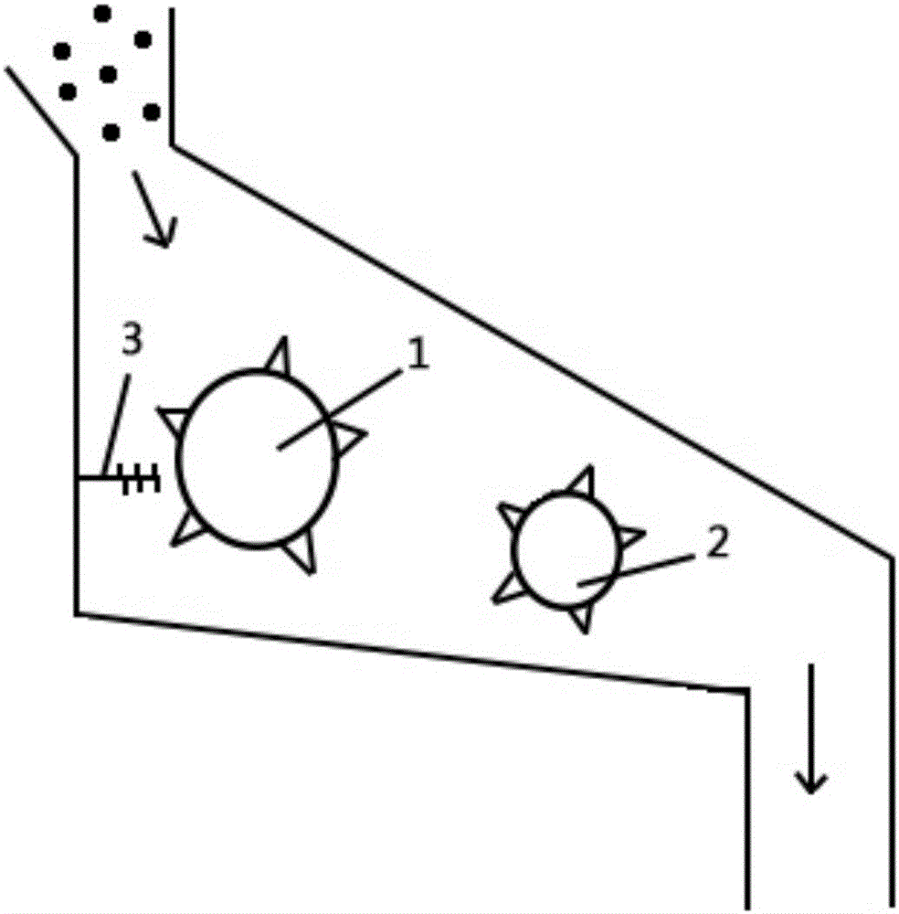
[0022] Such as figure 1 The rotary garbage crushing device shown includes the first five-knife roller 1, the second five-knife roller 2, a soft brush 3, a housing and an engine system; unbroken garbage enters from the entrance above the housing inside the housing, and successively pass through the first five-knife roller 1 and the second five-knife roller 2 for crushing, and then discharge from the outlet below the housing; the soft brush 3 is arranged on the left side of the first five-knife roller 1 The side is used to clean the flexible objects on the hob of the first five-blade roller 1, and the engine system drives the first five-blade roller 1 and the second five-blade roller 2 to rotate through a crankshaft connection;
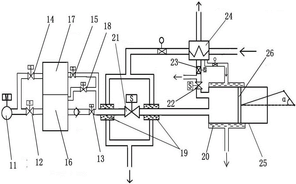
[0023] Such as figure 2As shown, the engine system includes an air compression pump 2, a compressed air tank, an intake solenoid valve 21, an engine, an exhaust solenoid valve 22, a heat exchange system and a control system, and the inside of the comp...
Embodiment 2
[0033] Such as figure 1 The rotary garbage crushing device shown includes the first five-knife roller 1, the second five-knife roller 2, a soft brush 3, a housing and an engine system; unbroken garbage enters from the entrance above the housing inside the housing, and successively pass through the first five-knife roller 1 and the second five-knife roller 2 for crushing, and then discharge from the outlet below the housing; the soft brush 3 is arranged on the left side of the first five-knife roller 1 The side is used to clean the flexible objects on the hob of the first five-blade roller 1, and the engine system drives the first five-blade roller 1 and the second five-blade roller 2 to rotate through a crankshaft connection;
[0034] Such as figure 2 As shown, the engine system includes an air compression pump 2, a compressed air tank, an intake solenoid valve 21, an engine, an exhaust solenoid valve 22, a heat exchange system and a control system, and the inside of the com...
Embodiment 3
[0044] Such as figure 1 The rotary garbage crushing device shown includes the first five-knife roller 1, the second five-knife roller 2, a soft brush 3, a housing and an engine system; unbroken garbage enters from the entrance above the housing inside the housing, and successively pass through the first five-knife roller 1 and the second five-knife roller 2 for crushing, and then discharge from the outlet below the housing; the soft brush 3 is arranged on the left side of the first five-knife roller 1 The side is used to clean the flexible objects on the hob of the first five-blade roller 1, and the engine system drives the first five-blade roller 1 and the second five-blade roller 2 to rotate through a crankshaft connection;
[0045] Such as figure 2 As shown, the engine system includes an air compression pump 2, a compressed air tank, an intake solenoid valve 21, an engine, an exhaust solenoid valve 22, a heat exchange system and a control system, and the inside of the com...
PUM
 Abstract
Description
Claims
Application Information