
Centrifugal pump impeller casting process

A centrifugal pump impeller and casting process technology, applied in the centrifugal pump impeller precision casting process and the multi-stage centrifugal pump field, can solve the difference in parameters such as increasing the calculated flow and head of the product, the impeller is difficult to reach the acceptance level, and it is difficult to control the blank shrinkage. Deformation and other problems, to achieve the effect of improving dimensional deformation that is difficult to control, reducing the risk of water leakage, and small deformation

Active Publication Date: 2016-08-10
重庆水泵厂有限责任公司
View PDF5 Cites 6 Cited by
  • Summary
  • Abstract
  • Description
  • Claims
  • Application Information

AI Technical Summary

Problems solved by technology

[0012] 3.1) Impact deformation, high temperature molten steel directly impacts the model in a short time, causing impact deformation
[0013] 3.2) The deformation during the solidification process is one of the processes with the largest amount of deformation. During the solidification shrinkage process, the shrinkage of the blade cover plate is hindered by the blade, and the deformation amount is small, but the central part shrinks without resistance, and the deformation proceeds along the axial direction, which in turn causes impeller overall deformation
[0014] In short, it is difficult to control the shrinkage and deformation of the blank by using the traditional center-no-casting process, which causes local shrinkage and deformation of the impeller, changes in the shape of the blade, and increases the difference between the product and the design calculation flow, head and other parameters, which makes it difficult for the impeller to achieve One of the root causes of the acceptance level

Method used


Image

  • Centrifugal pump impeller casting process
  • Centrifugal pump impeller casting process
  • Centrifugal pump impeller casting process

Examples


Embodiment Construction

[0034] The present invention will be described in detail below in conjunction with the accompanying drawings and specific embodiments.

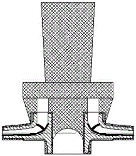
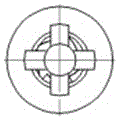
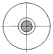
[0035] see Figure 4-Figure 5 , as can be seen from the figure, the core of the centrifugal pump impeller casting process of the present invention is the process of pouring according to the mold shell, and the mold shell has a central hole corresponding to the impeller shaft hole to be cast, so that the impeller shaft hole does not cast After casting, the impeller shaft hole is processed by cutting and other processes. The inner wall of the central hole of the formwork is evenly provided with 2-4 axial ribs along the circumference, so that a central columnar sprue and 2-4 split-flow inflows connected with the central columnar sprue are formed during pouring. The runner is formed by the area between two adjacent ribs during pouring. In the actual design, the ribs are 4 and form a 90° fan ring, so that the cross section of the cast impeller s...


PUM


Abstract

The invention discloses a centrifugal pump impeller casting process. The process of conducting pouring according to a mold shell is the core of the centrifugal pump impeller casting process. The mold shell comprises a central hole corresponding to a to-be-cast impeller shaft hole so that the impeller shaft hole cannot be cast out. The centrifugal pump impeller casting process is characterized in that 2-4 axial ribs are evenly arranged along the circumference of the inner wall of the central hole of the mold shell so that a central columnar straight spure and 2-4 diversion inner spures connected into a whole together with the central columnar straight spure can be formed during pouring; and each diversion inner spure is formed by the area between the two corresponding adjacent ribs during pouring. By means of the process, it can be ensured that the shape and size of a shell mold are stable in the precise casting process, and therefore the impeller deformation shrinkage during casting is reduced, the impeller finished product percent of pass is increased, the efficiency of centrifugal pumps is improved, and the service life of the centrifugal pumps is prolonged.

Description

technical field [0001] The invention relates to a multistage centrifugal pump, in particular to a centrifugal pump impeller precision casting process, which belongs to the technical field of centrifugal pump impeller casting. Background technique [0002] Centrifugal pumps have complex structures and high precision requirements, so they have very strict requirements on the casting process. Especially the high-speed centrifugal pump impeller, as one of the key components affecting the working efficiency of multi-stage centrifugal pumps, has higher requirements on casting technology. The correctness of the impeller shape directly affects the efficiency of centrifugal pumps, and the degree of fit between product accuracy and design dimensions is high. Uniformity is the most important factor to ensure the efficiency of centrifugal pumps. At present, manufacturers in the pump industry all adopt precision casting methods to reduce the deformation of the impeller. The precision ca...

Claims


Application Information

Patent Timeline
Patent Type & Authority Applications(China)
IPC IPC(8): B22C9/28B22C9/08
CPCB22C9/082B22C9/28
Inventor 王帆杨星旗穆磊何艳
Owner 重庆水泵厂有限责任公司
Learn More