
Ultra-soft metal foil belt edge trimming tool

A metal foil strip and soft metal technology, applied in the field of ultra-soft metal foil strip edge cutting knife, can solve the problems of large resistance, rough cutting edge, not sharp, etc., achieve the effect of improving stability and reliability, and solving roughness

Active Publication Date: 2016-08-10
格远电子科技(上海)有限公司
View PDF6 Cites 2 Cited by
  • Summary
  • Abstract
  • Description
  • Claims
  • Application Information

AI Technical Summary

Problems solved by technology

[0004] 1. Due to the limited flatness and sharpness of the cutting edge of traditional knives, the cutting edge cannot be finely ground, the processed surface is rough, and burrs are easy to occur and the burrs are large, which often need to be replaced, which increases the cost;
[0005] 2. The cutting edge is rough and not sharp. Therefore, the resistance during cutting is relatively large. If it is used for the processing of ultra-soft metal foil strips, the ultra-soft metal foil strips are easily cut or torn by the tool, and continuous processing cannot be performed;
[0006] 3. The two knife faces forming the blade are wide and without lubrication. When processing ultra-soft metal foil strips, it is easy to form metal materials and blades to bond, resulting in the basic failure of the knife to work normally.
[0007] Due to the low hardness and strength of ultra-soft metal foil, traditional cutting tools are only suitable for materials (such as stainless steel) with a thickness of more than 0.5mm, relatively high hardness and strength, and low processing surface requirements, which cannot meet the requirements of ultra-soft metal foil. Fine processing requirements such as continuous trimming of metal foil strips

Method used


Image

  • Ultra-soft metal foil belt edge trimming tool
  • Ultra-soft metal foil belt edge trimming tool
  • Ultra-soft metal foil belt edge trimming tool

Examples


Embodiment Construction

[0029] The technical solutions of the present invention will be further described below in conjunction with the accompanying drawings and embodiments.

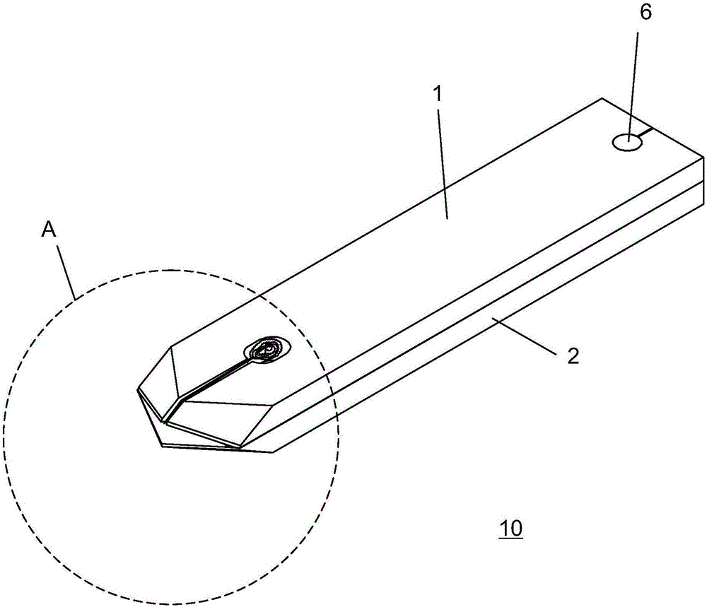
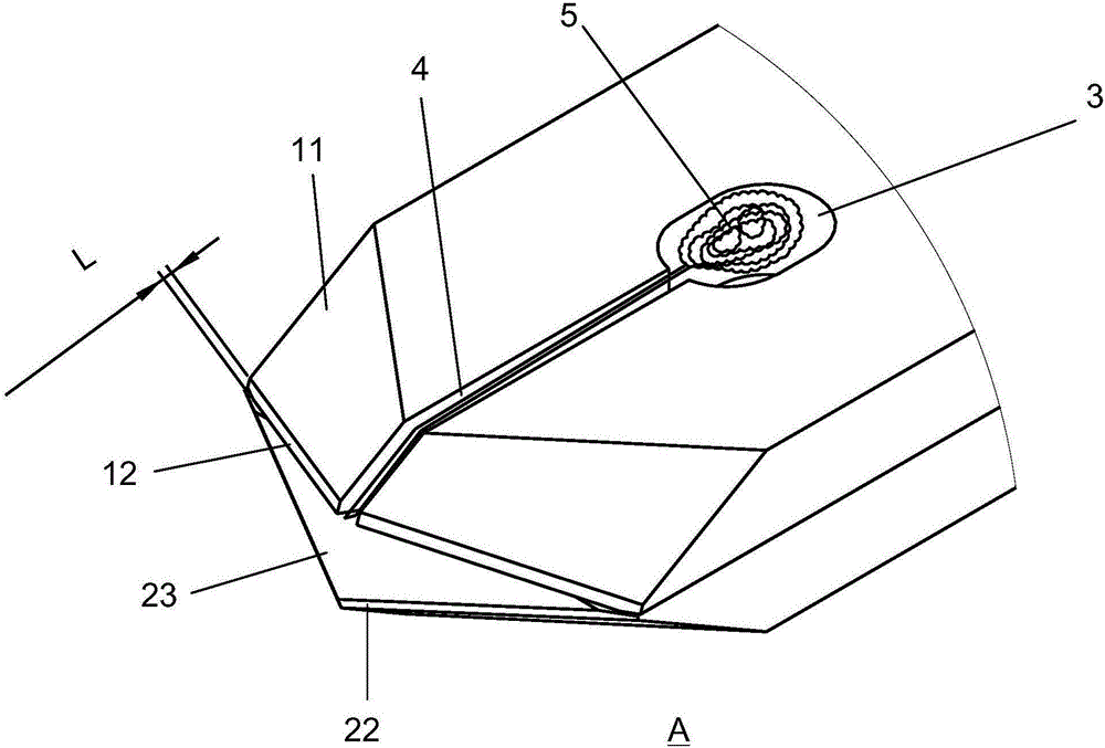
[0030] see Figure 1 ~ Figure 3 As shown, the ultra-soft metal foil band trimming knife 10 of the present invention comprises upper and lower blades 1,2, and the upper and lower blades 1,2 are stacked, and the tails of the upper and lower blades 1,2 are movably connected, and the upper and lower blades 1,2 are flexibly connected. 1. The heads of the lower blades 1 and 2 are in an isosceles triangle shape, and the upper surface of the upper blade 1 head is composed of the first wedge surface 11 and the second wedge surface 12 that are obliquely downward. The lower surface is formed by the obliquely upward third wedge surface 13, and the upper blade is jointly formed by the second and three wedge surfaces 12 and 13. The lower surface of the head is composed of the fourth wedge surface 21 and the fifth wedge surface 22 that are ...


PUM

PropertyMeasurementUnit
Widthaaaaaaaaaa

Abstract

The invention discloses an ultra-soft metal foil belt edge trimming tool. The ultra-soft metal foil belt edge trimming tool comprises an upper blade and a lower blade which are overlapped. The tail portion of the upper blade and the tail portion of the lower blade are movably connected. The head portion of the upper blade and the head portion of the lower blade are each in a triangular shape. The upper surface of the head portion of the upper blade is composed of a first wedge surface inclining downwards and a second wedge surface inclining downwards. The lower surface of the head portion of the upper blade is composed of a third wedge surface inclining upwards. An upper cutting edge is jointly formed by the second wedge surface and the third wedge surface. The structure of the head portion of the lower blade and the structure of the head portion of the upper blade are symmetric. By means of the edge trimming tool, the problems of cutting edge refined polishing, rough chamfered edge machining faces, large burrs, bonding of metal-class materials and the cutting edge and the like can be solved, and the stability and reliability of ultra-soft metal foil belt edge trimming are greatly improved.

Description

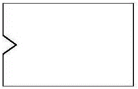
technical field [0001] The invention relates to a foil strip processing cutter, more specifically, relates to a supersoft metal foil strip edge trimming knife. Background technique [0002] Metal foil strip trimming technology is usually used in the field of auto parts production, and the trimming tools used are usually formed carbide blades or carbide knives for wire cutting edges (see figure 1 ), this type of tool is mainly used for edge trimming of hard or semi-hard stainless steel with a material thickness of 0.5mm or more. [0003] With the development and demand of the market, many products (such as aluminum battery tabs, etc.) need to use ultra-soft metal foil strip materials (thickness is usually 0.1 ~ 0.5mm, low hardness is usually below HV55, and tensile strength is usually 70 ~ 195 , such as pure aluminum HV20, pure copper HV55, etc.), and for the trimming of such ultra-soft metal foil materials, if the above-mentioned traditional trimming tool is used, there wil...

Claims


Application Information

Patent Timeline
IPC IPC(8): B26D1/00
CPCB26D1/0006B26D2001/0033B26D2001/006
Inventor 钱本富
Owner 格远电子科技(上海)有限公司
Learn More