

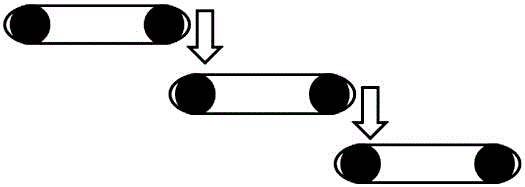
Linkage control method for multi-stage solid conveying equipment
A technology for conveying equipment and solids, which is applied in the direction of conveyor control devices, conveyor objects, transportation and packaging, etc., and can solve the problems of overflowing material consumption, unfavorable transmission equipment energy, slow response speed, etc.
- Summary
- Abstract
- Description
- Claims
- Application Information
AI Technical Summary
Problems solved by technology
Method used
Image

Examples
Embodiment 1
[0036] Example 1: PID Controller
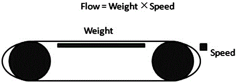
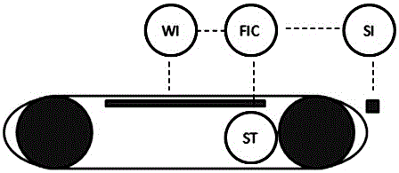
[0037] For the lowest-level conveying equipment, the flow signal is used as the controlled variable, and the speed is used as the manipulated variable to build a PID controller to realize the fixed value control of its flow. The parameters are set as follows: the ratio (P) needs to be adjusted according to the characteristics of the equipment, the integral time (I) should be between 1-10 seconds, and the differential time (D) should be between 0-5 seconds.
[0038] For the upper-level conveying equipment, the load of the lower-level conveying equipment is used as the controlled variable, and the speed of the adjacent upper-level conveying equipment is used as the manipulated variable to build a PID controller to realize the fixed value control of the load and connect them in turn. The parameters are set as follows: the ratio (P) needs to be adjusted according to the characteristics of the equipment, the integral time (I) should be between 100...
Embodiment 2
[0041] Example 2. Model Predictive Control
[0042] For the lowest-level conveying equipment, the flow signal is used as the controlled variable, and the speed is used as the manipulated variable to construct the MPC controller to realize the fixed value control of its flow. Its model should be a first-order model, determined by a step test.
[0043] For the upper-level conveying equipment, the load of the lower-level conveying equipment is used as the controlled variable, and the speed of the adjacent upper-level conveying equipment is used as the manipulated variable, and the MPC controller is constructed to realize the fixed value control of the load. Its model shall adopt integral model and be determined by step test.
[0044] As a preference, the flow rate of the lower-level conveying equipment can be used as a feed-forward signal of the load of the local conveying equipment and introduced into the control system to enhance the stability of the load signal control.
PUM
 Abstract
Description
Claims
Application Information