Hydraulic oil circulation cooling system of drilling machine

A technology of circulating cooling system and hydraulic oil, which is applied in the direction of fluid pressure actuating system components, mechanical equipment, fluid pressure actuating devices, etc., can solve problems such as high temperature cooling of oil, and achieve the effect of improving cooling efficiency

Active Publication Date: 2016-08-10
无锡市钻通工程机械有限公司
View PDF5 Cites 6 Cited by
  • Summary
  • Abstract
  • Description
  • Claims
  • Application Information

AI Technical Summary

Problems solved by technology

[0003] The purpose of the present invention is to overcome the deficiencies in the prior art and provide a hydraulic oil c...

Method used


Image

  • Hydraulic oil circulation cooling system of drilling machine

Examples


Embodiment Construction

[0010] The present invention will be further described below in conjunction with specific drawings.

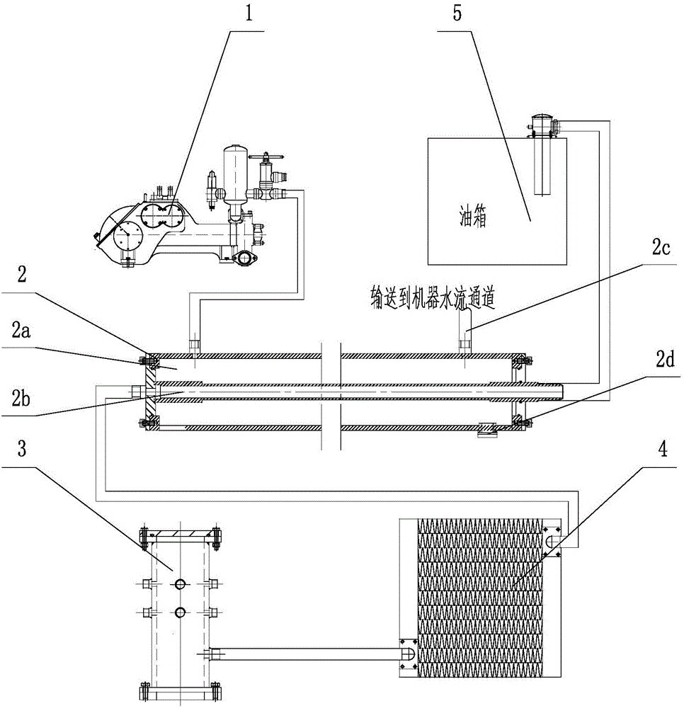
[0011] Such as figure 1 As shown: the drilling rig hydraulic oil circulation cooling system includes a mud pump 1, an oil return pipe device 2, a mud channel 2a, a hydraulic oil channel 2b, a water flow channel 2c, a drain plug 2d, an oil storage tank 3, an oil radiator device 4, and an oil tank 5 etc.

[0012] Such as figure 1 As shown, the drilling rig hydraulic oil circulation cooling system of the present invention includes an oil return pipe device 2, the oil return pipe device 2 includes a square pipe and a seamless steel pipe placed inside the square pipe, and the inner hole of the seamless steel pipe is a hydraulic oil channel 2b, A mud passage 2a is formed between the seamless steel pipe and the square pipe; one end of the square pipe is connected to the mud water pump 1 through a mud pipe, and the outlet of the other end of the square pipe is connected to the water...


PUM


Abstract

The invention relates to a hydraulic oil circulation cooling system of a drilling machine. The hydraulic oil circulation cooling system of the drilling machine is characterized by comprising an oil returning pipe device; the oil returning pipe device comprises a square pipe and a seamless steel pipe arranged on the inner side of the square pipe; an inner hole of the seamless steel pipe is a hydraulic oil channel; a slurry channel is formed between the seamless steel pipe and the square pipe; one end of the square pipe is connected with a slurry pump through a slurry pipeline; an outlet in the other end of the square pipe is connected with a water flow channel; one end of the hydraulic oil channel is connected with an oil tank through an oil pipe; the other end of the hydraulic oil channel is connected with an oil outlet of an oil radiator device through an oil pipe; and an oil inlet of the oil radiator device is connected with an oil storage tank. A drainage plug is arranged on the lower portion of the square pipe. The oil radiator device is a wind radiator and comprises a gear motor, blowing fan blades and a radiator. Water supplied by the slurry pump is effectively utilized to flow into the oil returning pipe, high-temperature oil inside the oil returning pipe is cooled along with water flow, and on the premise of not increasing the cost, the oil cooling efficiency is greatly improved.

Description

technical field [0001] The invention relates to a drilling rig hydraulic oil circulation cooling system, which belongs to the technical field of hydraulic systems. Background technique [0002] With the continuous development and progress of social science and technology, the construction machinery industry is also growing rapidly, and the hydraulic system is also widely used with the continuous updating of construction machinery and equipment. The hydraulic system is undoubtedly the core part of the whole equipment. During the operation of the hydraulic system, due to mechanical loss and volume loss, it will cause the system to heat up. The heat generated by the system will increase the temperature of the oil, and the high oil temperature will make the hydraulic power components And the performance of the executive components is reduced, and serious components can be damaged. High-temperature cooling of oil has always been a problem that has been concerned and must be solv...

Claims


Application Information

Patent Timeline
IPC IPC(8): F15B21/04
CPCF15B21/041F15B21/042
Inventor 董志伟徐彬彬贾绍宽
Owner 无锡市钻通工程机械有限公司
Why Eureka
Try Eureka