
Self-locking type hinge and cubic star battery array adopting self-locking type hinge

A cubic star battery and self-locking technology, applied in the direction of electrical components, photovoltaic power generation, pivot connection, etc., can solve the problems of large distance between the deployment array and the body mounting plate, increase the launch cost, and the cube star is stuck, and achieve a larger Accept the illuminated area, reduce the launch cost, and expand the effect of large area

Inactive Publication Date: 2016-08-10
NANJING UNIV OF SCI & TECH
View PDF8 Cites 5 Cited by
  • Summary
  • Abstract
  • Description
  • Claims
  • Application Information

AI Technical Summary

Problems solved by technology

This design has the following defects: (1) the size is large, resulting in a large distance between the deployment array and the body mounting plate, the cube star may be stuck in the separation mechanism, and the launch fails; (2) the mass is large, limiting the mass of the load carried by the cube star, Increase the launch cost; (3) Low adaptability, the deployment array can only be deployed at an angle of 90° to the body mounting plate, making the deployment array poorly irradiated by sunlight and generating less electricity; (4) Poor portability, and can only be used for dual Unit cube star, can not be used for multi-unit cube stars such as three units

Method used


Image

  • Self-locking type hinge and cubic star battery array adopting self-locking type hinge
  • Self-locking type hinge and cubic star battery array adopting self-locking type hinge
  • Self-locking type hinge and cubic star battery array adopting self-locking type hinge

Examples


Embodiment 1

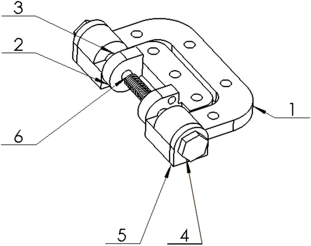
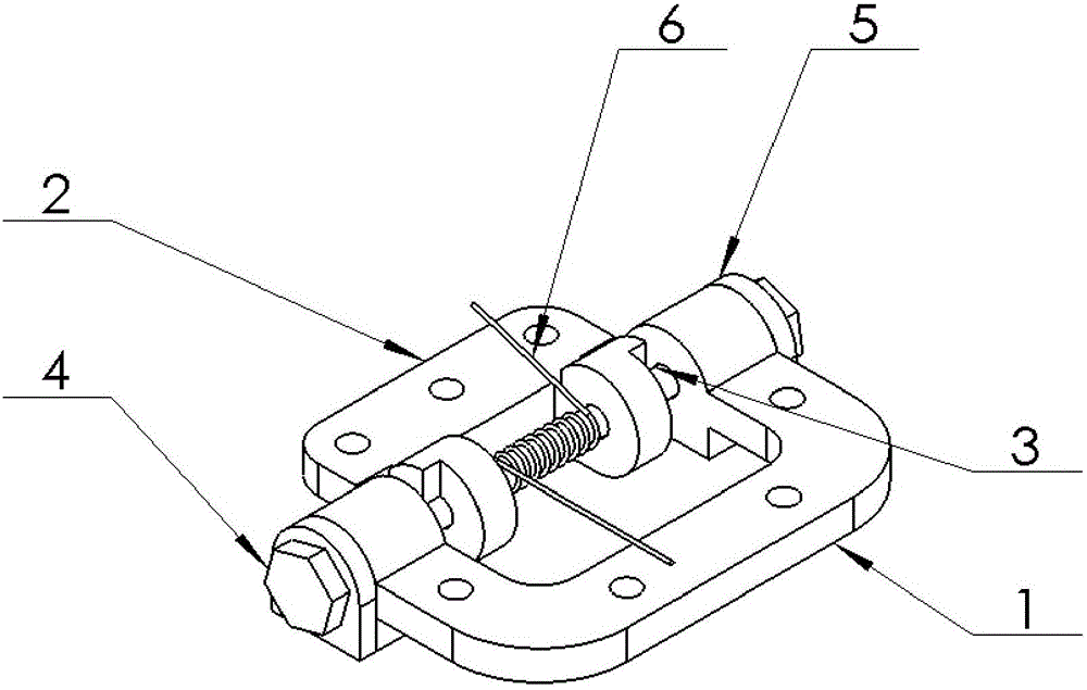
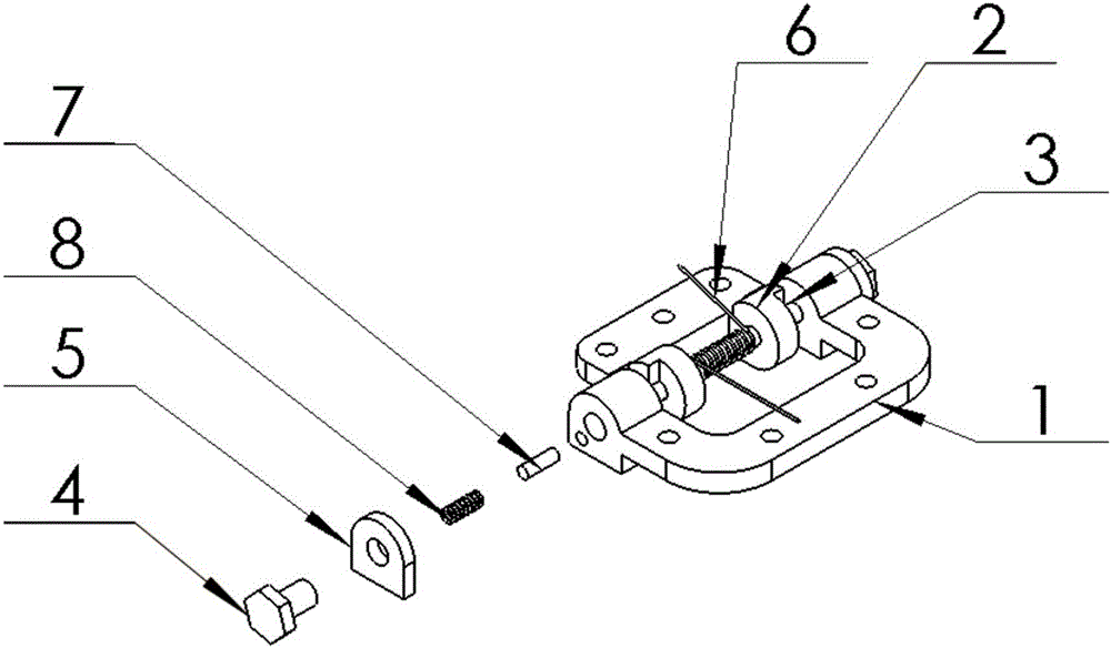
[0031] to combine Figure 1~Figure 7 , a cube star battery array using self-locking hinges, taking 3 panels and 2 self-locking hinges as an example, the 3 panels are arranged in three rows, and the panels between the rows pass through Self-locking hinge connection, between the columns in the second row is connected by a self-locking hinge, the self-locking hinge connecting the first row and the second row of battery panels is connected to the second row and the third row The self-locking hinges of the battery board are located on both sides of the battery board; the self-locking hinges on the second adjacent column are located on both sides of the battery board. The cell arrays located on both sides of the cube star are symmetrical about the centroid of the cube star after unfolding.

[0032] A battery array that can be folded and unfolded multiple times for a cube star, including a body mounting plate fixing part 1, a deployment array fixing part 2, a positioning shaft 3, a ...

Embodiment 2

[0034] combine Figure 1~Figure 6 as well as Figure 8 : A cubic star battery array using self-locking hinges, taking 6 battery panels and 6 self-locking hinges as an example, the 6 battery panels are divided into three rows and two columns, and the battery panels between the rows Connected by self-locking hinges, the columns in the second row are connected by self-locking hinges, the self-locking hinges connecting the first row and the second row of battery panels are connected to the second row and the third row The self-locking hinges of the first row of battery panels are located on both sides of the battery panel; the self-locking hinges of the second adjacent column are located on both sides of the battery panel. The cell arrays located on both sides of the cube star are symmetrical about the centroid of the cube star after unfolding.

[0035] A battery array that can be folded and unfolded multiple times for a cube star, including a body mounting plate fixing part 1, ...

Embodiment 3

[0036] Example 3: Combining Figure 1~Figure 6 as well as Figure 9 , a cube star battery array using self-locking hinges, taking 9 battery panels and 10 self-locking hinges as an example, the 9 battery panels are divided into three rows and three columns, and the battery panels between the rows Connected by self-locking hinges, the columns in the second row are connected by self-locking hinges, the self-locking hinges connecting the first row and the second row of battery panels are connected to the second row and the third row The self-locking hinges of the first row of battery panels are located on both sides of the battery panel; the self-locking hinges of the second adjacent column are located on both sides of the battery panel. The cell arrays located on both sides of the cube star are symmetrical about the centroid of the cube star after unfolding.

[0037] A battery array that can be folded and unfolded multiple times for a cube star, including a body mounting plate ...


PUM


Abstract

The invention discloses a self-locking type hinge and a cubic star battery array adopting the self-locking type hinge. The self-locking type hinge comprises a body inserting panel fixing part, unfolding array fixing parts, a positioning shaft, screws, locking pieces, a torsional spring, positioning pins, springs and limiting protrusions. Under drive of torsional spring force, the unfolding array fixing parts rotate around the body inserting panel fixing parts, and when the unfolding array fixing parts are unfolded to the set angle, the springs pop the positioning pins into blind holes from through holes so as to achieve the positioning effect; the cubic star battery array adopts the hinge of the type, and the battery array comprises 3P battery plates and a plurality of self-locking type hinges, wherein the P is equal to 1, 2, 3 and the like, the battery plates are equally divided into three rows, and the rows are connected through the hinges; the hinge connecting the first row of battery plates and the second row of battery plates and the hinge connecting the second row of battery plates and the third row of battery plates are located on the two faces of the battery plates, and the column of the second row and another columns are connected through the hinges; and the hinges on the adjacent columns are located on the two faces of the battery plates; and the self-locking type hinge and the cubic star battery array are small in size, small in mass, high in adaptation, good in transportability and large in unfolding area.

Description

technical field [0001] The invention belongs to the technical field of cube stars, and in particular relates to a self-locking hinge and a cube star battery array using the self-locking hinge. Background technique [0002] In recent years, with the rapid development of technologies such as communications, optoelectronic components, materials, sensors, and applied fluids, the development of CubeSat technology has accelerated significantly, and it has become possible to use CubeSats for remote measurement and testing. The low cost has prompted the emergence of cubesat development programs around the world. [0003] The power supply is a very important subsystem of CubeSat, including battery packs and solar arrays. It provides the required working energy for the cube star, and the solar array is the only direct source of energy. It converts sunlight into electrical energy to power the loads on the star, and at the same time it can also charge the battery pack that maintains t...

Claims


Application Information

Patent Timeline
IPC IPC(8): F16C11/04H02S30/20
CPCF16C11/04H02S30/20Y02E10/50
Inventor 张晓华张翔苇桑艾尔-马伊江涛廖文和于永军莫乾坤郑侃
Owner NANJING UNIV OF SCI & TECH
Learn More