Optical system applied to laser interferometer measuring guide rail linearity

A laser interferometer and optical system technology, applied in the field of optical systems, can solve problems such as frequency stabilization, and achieve the effects of saving space, simple mechanical structure, and simplified design

Active Publication Date: 2016-08-10
CHOTEST TECH INC
View PDF7 Cites 12 Cited by
  • Summary
  • Abstract
  • Description
  • Claims
  • Application Information

AI Technical Summary

Problems solved by technology

But in this way, due to the reason of the light return component, some light enters the laser interferometer, which will cause the stability of the laser system

Method used


Image

  • Optical system applied to laser interferometer measuring guide rail linearity
  • Optical system applied to laser interferometer measuring guide rail linearity
  • Optical system applied to laser interferometer measuring guide rail linearity

Examples


Embodiment Construction

[0024] The preferred embodiments of the present invention will be further described in detail below in conjunction with the accompanying drawings.

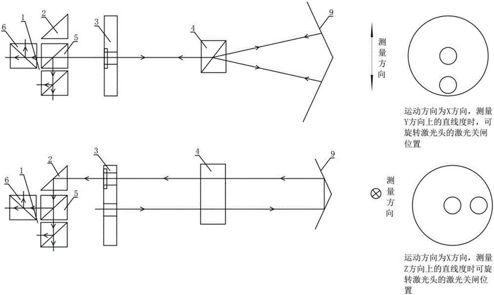
[0025] Such as figure 1 As shown, this example provides an optical system for measuring the straightness of a guide rail with a laser interferometer, including: a detection optical assembly 1, an optical steering mirror 2, a rotatable laser head 3 and an external optical path assembly, and the light beam passes through the detection optical assembly 1 to achieve dual-channel optical detection, the optical steering mirror 2 is used to realize the downward movement and steering of the beam to meet the detection requirements of the detection optical assembly 1, and the rotatable laser head 3 is arranged on the detection optical assembly 1 and the rotatable return optical part between the outer optical path assembly for measuring the outer optical path of the optical system.

[0026] The laser interferometer is an optical measuring ...


PUM


Abstract

The invention provides an optical system applied to a laser interferometer measuring guide rail linearity. The optical system comprises a detecting optical assembly, an optical turning mirror, a rotatable laser head and a reflector path assembly, wherein two channel optical detection can be conducted on light beams via the detecting optical assembly, the optical turning mirror is used for moving down and turning the light beams, and therefore detecting requirements of the detecting optical assembly can be met; the rotatable laser head is a rotatable light returning part arranged between the detecting optical assembly and the reflector path assembly, and the reflector path assembly is used for measuring a reflector path of the optical system. According to the optical system disclosed in the invention, setting and steps of linearity measurement in a vertical direction are greatly simplified via the three dimensional optical turning mirror; two channel optical detection is realized via the detecting optical assembly, optical elements of the optical system are simplified and are used to a maximum extent, instrument design space is saved, laser light returning holes of the rotatable laser head are reasonably designed, and existing hole sites are fully used.

Description

technical field [0001] The invention relates to an optical system, in particular to an optical system for measuring the straightness of a guide rail by a laser interferometer. Background technique [0002] In the prior art, the laser interferometer measures the straightness of the guide rail using such as figure 2 and image 3 the way shown, in the figure 2 In the process, the laser light exits from the laser head and is divided into two beams in the horizontal direction at the Wollaston prism. The two beams pass through the reflector and are reflected back to the Wollaston prism, and then combined into one beam through the Wollaston prism and returned to the laser. When measuring, you can move the reflector or the Wollaston prism. When there is a relative deviation between the measurement axis and the optical axis during the movement, it can be recorded by the electronic system in the laser head to obtain this change value, and then Obtain the straightness information o...

Claims


Application Information

Patent Timeline
IPC IPC(8): G01B11/27G01B9/02
CPCG01B11/26G01B11/27G01B9/02015
Inventor 刘龙为张和君张珂陈源
Owner CHOTEST TECH INC
Why Eureka
Try Eureka