Antenna

An antenna and radiating element technology, applied in the directions of antennas, radiating element housings, electrical components, etc., can solve the problems of poor beam convergence, complex structure, poor stability, etc., to improve the cross-polarization ratio, good beam convergence, and improve radiation. performance effect

Active Publication Date: 2016-08-10
COMBA TELECOM TECH (GUANGZHOU) CO LTD
View PDF6 Cites 5 Cited by
  • Summary
  • Abstract
  • Description
  • Claims
  • Application Information

AI Technical Summary

Problems solved by technology

[0003] However, the current antenna, on the one hand, has a complex structure, which increases the difficulty of processing and assembly; on the other hand, it has poor stability and poor beam convergence, and cannot achieve high performance indicators.

Method used


Image

  • Antenna
  • Antenna
  • Antenna

Examples


Embodiment Construction

[0027] Embodiments of the present invention are described in detail below, examples of which are shown in the drawings, wherein the same or similar reference numerals designate the same or similar elements or elements having the same or similar functions throughout. The embodiments described below by referring to the figures are exemplary only for explaining the present invention and should not be construed as limiting the present invention.

[0028] As used hereinafter, "low frequency" refers to lower frequency bands, such as 790MHz-960MHz, and "high frequency" refers to higher frequency bands, such as 1710MHz-2690MHz. A "low frequency radiating element" refers to a radiating element for such a lower frequency band, and a "high frequency radiating element" refers to a radiating element for such a higher frequency band. "Dual frequency" in the full text, includes the above-mentioned low frequency and high frequency.

[0029] The ultra-wideband referred to below means that the...


PUM


Abstract

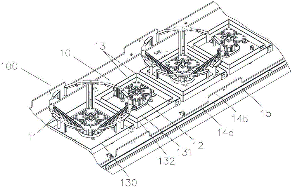
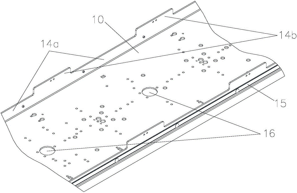
The invention provide an antenna which comprises a reflecting plate having a front side, a pair of side plates, low frequency radiation units, high frequency radiation units and a reflection cavity of at least one layer which surrounds the outer sides of the high frequency radiation units, wherein the side plates are respectively arranged at two sides, positioned in a width direction, of the reflecting plate and extend upward from the front side of the reflecting plate; the low frequency radiation units and the high frequency radiation units are arranged on the front side of the reflecting plate, one high frequency radiation unit is arranged between two adjacent low frequency radiation units, and a two layer reflection cavity is arranged at the outer side of at least one high frequency radiation unit. Compared with technologies of the prior art, the antenna of the invention is advantageous in that a double layer or one layer reflection cavity surrounds the high frequency radiation units, high horizontal plane wave beam convergence is realized, and high performance of the high frequency radiation units can be achieved.

Description

technical field [0001] The invention relates to the technical field of antennas in mobile communications. Specifically, the present invention relates to an antenna that can realize ultra-wideband dual-frequency dual-polarization and concealment functions. Background technique [0002] With the gradual maturity of 4G mobile communications, the society's demand for broadband antennas is increasing day by day. The capacity and quality of mobile communication systems are continuously upgraded, which puts forward higher and higher performance requirements for base station antennas. In recent years, wide-band, multi-frequency, miniaturized and concealed antennas are increasingly favored by people. [0003] However, the current antenna, on the one hand, has a complex structure, which increases the difficulty of processing and assembly; on the other hand, it has poor stability and poor beam convergence, and cannot achieve high performance indicators. Contents of the invention ...

Claims


Application Information

Patent Timeline
Patent Type & Authority Applications(China)
IPC IPC(8): H01Q1/42H01Q15/16
CPCH01Q1/42H01Q15/16
Inventor 陶世强胡成才黄明达刘聪游建军
Owner COMBA TELECOM TECH (GUANGZHOU) CO LTD
Why Eureka
Try Eureka