Distal femur cutting assembly and ectropion positioning device
A positioning device and distal technology, applied in medical science, surgery, etc., can solve the problems of large space required for intramedullary rod instruments, high production costs, and difficulty in thorough cleaning, and achieve low production costs, convenient disassembly and assembly, Easy to use and maintain, reliable effect
- Summary
- Abstract
- Description
- Claims
- Application Information
AI Technical Summary
Problems solved by technology
Method used
Image

Examples
no. 1 example
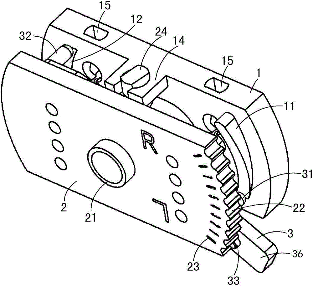
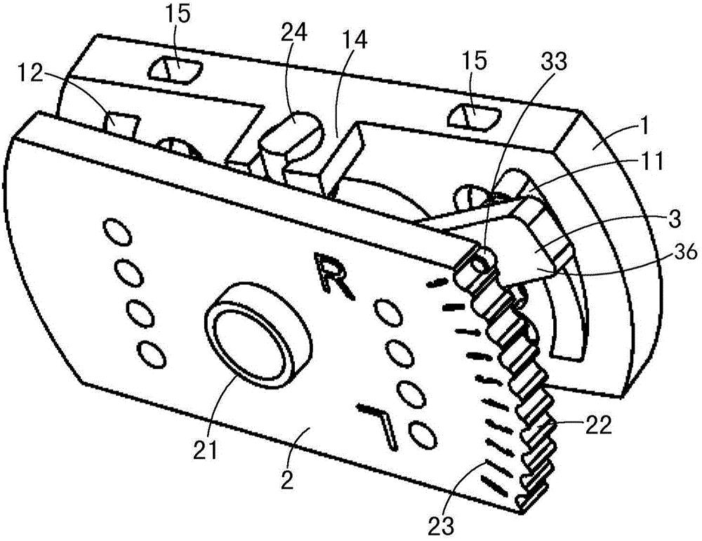
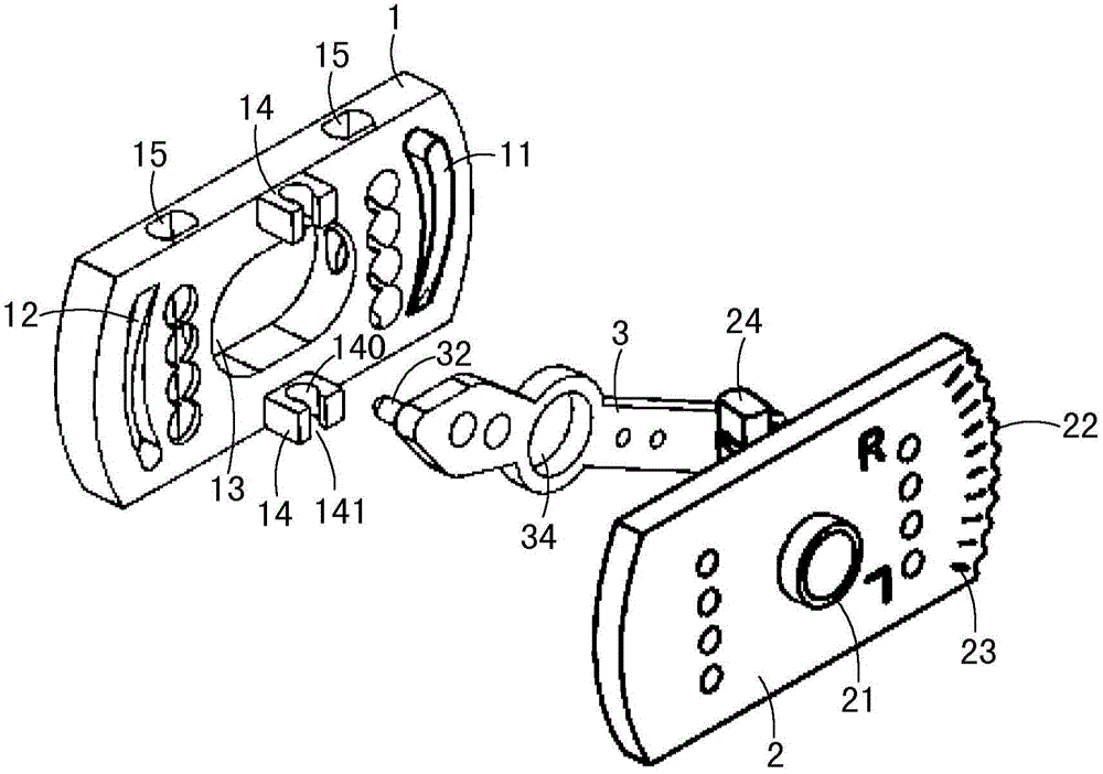
[0032] Such as figure 1 , figure 2 with image 3 As shown, the valgus positioning device in this embodiment includes a rotating plate 1 , a fixed plate 2 and an operating member 3 .
[0033] Wherein, the rotating plate 1 is a flat plate structure, and a through hole 13 is arranged at the center of the rotating plate 1, and two ear plates 14 are arranged on the upper and lower sides of the through hole 13, and each ear plate 14 is provided with a through hole. 140 , the centerlines of the two through holes 140 coincide, and the two through holes 140 are provided with a notch 141 at the same position, and the notch 141 is smaller than the inner diameter of the circular hole 140 and becomes the entrance of the circular hole 140 . A first adjustment part 11 and a second adjustment part 12 are respectively provided on the left and right sides of the through hole 13 , and both the first adjustment part 11 and the second adjustment part 12 extend along the vertical direction of th...
no. 2 example
[0042] The main structure of this embodiment is the same as that of the first embodiment, and the differences will be described below.
[0043] Such as Figure 7 with Figure 8 As shown, in this embodiment, both the first adjusting part 11 and the second adjusting part 12 are half convex and half concave, and the convex part and the concave part transition smoothly to form a slope. The unevenness of the first adjusting part 11 and the second adjusting part 12 relative to the inner surface of the rotating plate 1 is symmetrical with respect to the intersection of the center line of the through hole 13 and the inner surface of the rotating plate 1 . Both the first abutting portion 31 and the second abutting portion 32 are protrusions protruding from the operation member 3 .
[0044] In this embodiment, when the boss of the first abutment part 31 is located at the middle plane of the first adjustment part 11, the protrusion of the second abutment part 32 is located at the middl...
no. 3 example
[0052] In the above two embodiments, the operating member 3 is rotatably installed between the fixed plate 2 and the rotating plate 1 , but other implementations are also possible. For example, the first adjustment part 11 and the second adjustment part 12 on the rotating plate 1 are still designed to be convex or concave relative to the plane, but they are not arc-shaped, but linear. The way of sliding linear guide rail is to slide up and down between the fixed plate 2 and the rotating plate 1, and the sliding track is parallel to the turning line of the fixed plate 2 and the rotating plate 1. A positioning groove 22 is provided on the surface of the fixed plate 2 relative to the rotating plate 1 for adjustment and positioning of the operating member 3 . The first abutting part 31 of the operating member 3 cooperates with the first adjustment part 11 and the second abutment part 32 cooperates with the second adjustment part 12, and the projections of the first adjustment part...
PUM
 Abstract
Description
Claims
Application Information
 - R&D
- Intellectual Property
- Life Sciences
- Materials
- Tech Scout
- Unparalleled Data Quality
- Higher Quality Content
- 60% Fewer Hallucinations
Browse by: Latest US Patents, China's latest patents, Technical Efficacy Thesaurus, Application Domain, Technology Topic, Popular Technical Reports.
© 2025 PatSnap. All rights reserved.Legal|Privacy policy|Modern Slavery Act Transparency Statement|Sitemap|About US| Contact US: help@patsnap.com