
Feeding system for settling tank

A feeding system and settling tank technology, applied in the field of separation, can solve the problems of wasting flocculants, increased production costs, and low solid content in the underflow, and achieve the effects of improving the efficiency of sedimentation separation, prolonging the residence time, and increasing the solid content in the underflow

Inactive Publication Date: 2016-08-17
CENT SOUTH UNIV
View PDF9 Cites 1 Cited by
  • Summary
  • Abstract
  • Description
  • Claims
  • Application Information

AI Technical Summary

Problems solved by technology

[0003] For the situation where the solid particle content in the industrial feed liquid continues to increase, the existing flat-bottomed settling tank cannot completely settle the particles in the feed liquid, and the settling speed is slow, resulting in low solid content in the underflow and unsatisfactory separation effect
If the amount of flocculant is increased blindly, not only will the problem not be solved, but too much flocculated floating matter will enter the overflow, increasing the viscosity of the overflow and the content of floating matter in the clear liquid, which will bring great harm to the subsequent leaf filter and other processes. Additional burden and waste of flocculant, resulting in increased production costs

Method used


Image

  • Feeding system for settling tank
  • Feeding system for settling tank
  • Feeding system for settling tank

Examples


Embodiment 1

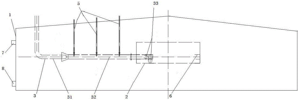
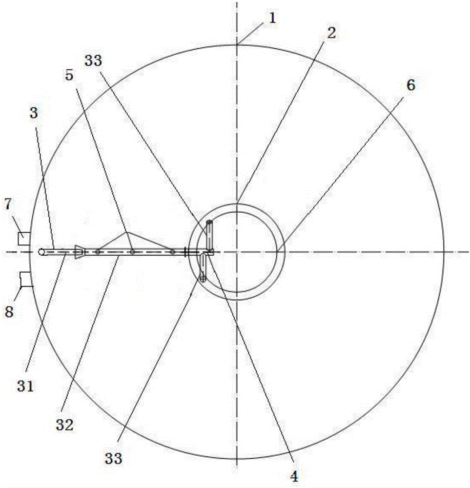
[0037] See Figure 1-Figure 3 , A feeding system for a settling tank, comprising a feeding connecting piece 3, the feeding connecting piece 3 comprising a front feed pipe 31 communicating with an external feeding device, and a rear section communicating with the front feeding pipe 31 The feed pipe 32 and the two feed pipes 33 both connected with the rear feed pipe 32, the outlet end of the rear feed pipe 32 and the feed pipe 33 are coaxially arranged in the settling tank Inside the central barrel 2 inside the tank body 1, the inlet ends of the front-stage feeding pipe 31 and the rear-stage feeding pipe 32 are located outside the central barrel 2 and inside the settling tank body 1 .

[0038] The upper part of the sedimentation tank body 1 is provided with an overflow port 7, and the lower part is provided with an underflow outlet 8. The diameter of the sedimentation tank body 1 is Φ15m-40m, and the height is 6m-10m; the diameter of the central barrel 2 is Φ3m- 6m, the height is...

Embodiment 2

[0049] The difference between this embodiment and the first embodiment is only that the positions of the two feed pipes are different, specifically: the central axis of the rear feed pipe 32 and the central axis of one feed pipe 33 are located at A On the plane, the central axis of the rear feed pipe 32 and the central axis of the other feed pipe 33 are located on the B plane, and the A plane and the B plane are two different planes. The angle between the central axis of the tube 33 is 15°, see Figure 4 .


PUM

PropertyMeasurementUnit
diameteraaaaaaaaaa
heightaaaaaaaaaa
diameteraaaaaaaaaa

Abstract

The invention provides a feeding system for a settling tank. The feeding system comprises a feeding connector which comprises a front feeding pipe, a rear feeding pipe and distribution pipes. An outlet end of the rear feeding pipe penetrates the side wall of a center barrel and is positioned inside the center barrel, a partition is arranged inside the outlet end of the rear feeding pipe, and flocculant feeding pipes are arranged on the rear feeding pipe. By combination design of the flocculant feeding pipes, the partition and the distribution pipes, dissolved diluted feed liquid enters the rear feeding pipe to be completely contacted and quickly mixed with flocculant, mixed feed liquid is distributed by the partition to flow into the two distribution pipes to enter the center barrel, on the one hand, the feed liquid in the center barrel can be rotatably stirred, and on the other hand, stay duration of the feed liquid in the center barrel is prolonged, remixing, contacting, adsorption and sedimentation of the feed liquid and the flocculant in the center barrel are enhanced, settling separation efficiency is improved, flocculant consumption is reduced, underflow solid content is increased, productivity is improved, and production cost is reduced.

Description

Technical field [0001] The invention relates to the technical field of separation, in particular to a feeding system for a sedimentation tank. Background technique [0002] In the existing flat-bottom sedimentation tank, the material enters the central barrel through the feed pipe, and the flocculant is also added to the material liquid. The material is mixed and adsorbed with the flocculant in the central barrel, and enters the sedimentation tank gently, and is Under the action, it sinks to the bottom of the tank, and the supernatant liquid flows out of the overflow pipe through the overflow cofferdam, and the settled solids are discharged from the underflow pipe. In this process, it is hoped that the solid particles can settle as quickly as possible, the overflow obtained is as clear as possible, and red mud with high solid content is obtained, so as to reduce the washing times in the subsequent washing section and the consumption of washing water. [0003] Regarding the situati...

Claims


Application Information

Patent Timeline
Patent Type & Authority Applications(China)
IPC IPC(8): B01D21/01B01D21/02B01D21/24
CPCB01D21/01B01D21/2405
Inventor 李茂高玉婷
Owner CENT SOUTH UNIV
Learn More