An impurity separation device for petroleum storage tanks

A separation device and oil storage tank technology, which is applied in the field of oil storage tanks, can solve the problems of difficult cleaning of oil storage tank deposits, and achieve the effects of avoiding use costs, reducing floor space, and rapid separation

Active Publication Date: 2018-05-29
湛江港石化码头有限责任公司
View PDF12 Cites 0 Cited by
  • Summary
  • Abstract
  • Description
  • Claims
  • Application Information

AI Technical Summary

Problems solved by technology

Currently, there is a lack of a good oil cleaning device and related methods in the market, and it is impossible to realize the problem that the sediment at the bottom of the oil storage tank is not easy to clean

Method used


Image

  • An impurity separation device for petroleum storage tanks
  • An impurity separation device for petroleum storage tanks

Examples


Embodiment 1

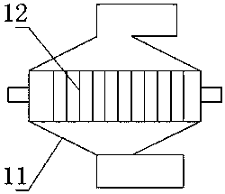
[0028] Such as figure 1 Shown, the impurity separating device that is used for petroleum storage tank of the present invention comprises the spindle-shaped separator that vertically arranges; The separator is divided into heavy region, medium region, and light region from bottom to top; A heavy outlet is set in the quality area, a light outlet is set in the light area, a separation outlet and a separation inlet are respectively set on opposite sides of the middle area, and a buffer device is provided in the middle area, and the buffer device includes a buffer frame and A plurality of flexible buffer bars; the buffer bars are vertically arranged in the separator and fixed by the buffer frame.

[0029] The heavy area is funnel-shaped, the light area is cone-shaped, and the height ratio of the heavy area, the medium area, and the light area is (2-4): (6-8): (1-3); On average, there are 80-110 buffer strips per cubic meter in the medium quality area. This structure can facilitat...

Embodiment 2

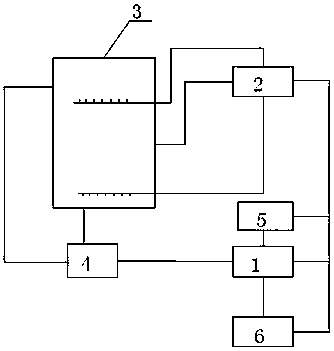
[0035] Such as figure 2 As shown, the filter system based on the separation device of embodiment 1 includes an oil tank body 3, a mixer 4, a first filter 5, and a second filter 6; the separation device includes a first separator 1 and a second separator 2; The mixer 4 is connected to the upper part and the bottom of the oil tank body 3 through pipelines and respectively extracts the oil from the upper part and the lower part of the oil tank body 3 for mixing, and the output end of the mixer 4 is connected to the first separator 1, the second The separation outlet of a separator 1 communicates with the separation inlet of the second separator 2, the heavy outlet communicates with the separation inlet of the second separator 2 through the second filter 6, and the light outlet communicates with the second separator 2 through the first filter 5. The separation inlet of the separator 2 is connected; the separation outlet of the second separator 2 is connected to the middle part of...

Embodiment 3

[0037] Based on the filtering system of the separating device of embodiment 2, its filtering method:

[0038] Step 1: The oil at the top and bottom of the oil tank body 3 is mixed evenly through the pipeline at a ratio of 1.3-1.8, and the mixed oil is sprayed into the first separator 1 at a speed of 15-18m / s under the action of the oil pump In the quality area, after the oil is fully decelerated under the action of the buffer strip, the heavy impurities in the oil fall to the heavy area, and the light impurities in the oil float up to the light area;

[0039] Step 2: The oil after impurity separation enters the second separator 2 through the separation outlet, and the oil in the heavy area enters the first filter 5 and flows into the second separator 2 after being filtered by impurities, and the oil in the light area enters the second separator 2. The oil enters the second filter 6 and flows into the second separator 2 after being filtered by impurities;

[0040] Step 3: The ...


PUM


Abstract

The invention discloses an impurity separating device used for a petroleum storage tank, and belongs to the field of petroleum storage tanks. The impurity separating device comprises a vertical spindle-shaped separator, wherein the separator is divided into a heavy impurity region, a middle impurity region and a light impurity region from top to bottom; a heavy impurity outlet is formed in the heavy impurity region; the light impurity outlet is formed in the light impurity region; a separating outlet and a separating inlet are separately formed in the opposite two sides of the middle impurity region; a buffer device is arranged in the middle impurity region and comprises a buffer frame and a plurality of flexible buffer strips; the buffer strips are vertically arranged in the separator and are fixed through the buffer frame. In the separator, impurities are quickly decelerated, so that vortexes can be formed in the areas of the buffer strips, the vortexes at different parts easily generate collision, the impurities with different weights are separated in the vortexes under the action of centrifugal force, and the impurity separating speed is increased by 3-5 times in comparison with that under the action of gravity. The spindle type design can reduce floor space of the impurity separating device, and can be beneficial for discharging separated impurities.

Description

technical field [0001] The invention relates to an impurity separation device for petroleum storage tanks, belonging to the field of petroleum storage tanks. Background technique [0002] After the oil storage tank has been used for a period of time, the impurities in the crude oil will deposit on the bottom and wall of the tank, which will reduce the effective capacity of the oil storage tank and affect the efficiency of the oil storage tank. Therefore, the oil storage tank needs to be inspected, repaired and cleaned regularly Internal sludge, the current domestic traditional oil tank cleaning method mainly uses manual labor, and manual tank cleaning has problems such as high labor intensity, long construction period, poor safety, low crude oil recovery rate, and environmental pollution. With the construction of a large number of large oil storage tanks in my country and the increasing emphasis on environmental protection issues, manual cleaning of tanks no longer meets the...

Claims


Application Information

Patent Timeline
Patent Type & Authority Patents(China)
IPC IPC(8): B01D36/04C08L25/10C08L15/00C08L23/20C08L23/22C08L45/00C08K13/02B03C1/30
CPCB01D36/045B03C1/30C08L25/10C08L2205/035C08L15/00C08L23/22C08L45/00C08K13/02
Inventor 方俊莫希明洪斌陈其
Owner 湛江港石化码头有限责任公司
Why Eureka
Try Eureka