Stirring device

A technology of a stirring device and a stirring shaft, which is applied to mixers with a rotating stirring device, accessories of the mixer, transportation and packaging, etc. The effect of expanding the stirring range and reducing the dead angle

Inactive Publication Date: 2016-08-17
TONGLING BAIRUI EQUIP PARTS CO LTD
View PDF5 Cites 5 Cited by
  • Summary
  • Abstract
  • Description
  • Claims
  • Application Information

AI Technical Summary

Problems solved by technology

The stirring shaft of the stirring device currently used cannot be lifted up and down, and the stirring efficiency is low. There is a dead angle at the bottom of the stirring tank during work, and the stirring is uneven, and the effect is not ideal. In addition, the rubber will generate heat during the stirring process. Heat loss will affect the production quality of rubber seals, and ultimately affect the use of rubber seals

Method used


Image

  • Stirring device
  • Stirring device

Examples


Embodiment Construction

[0012] The present invention will be further described below in conjunction with the embodiments and the accompanying drawings.

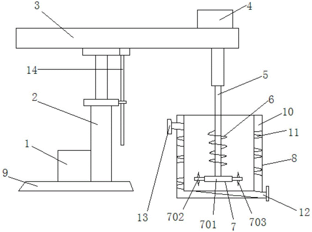
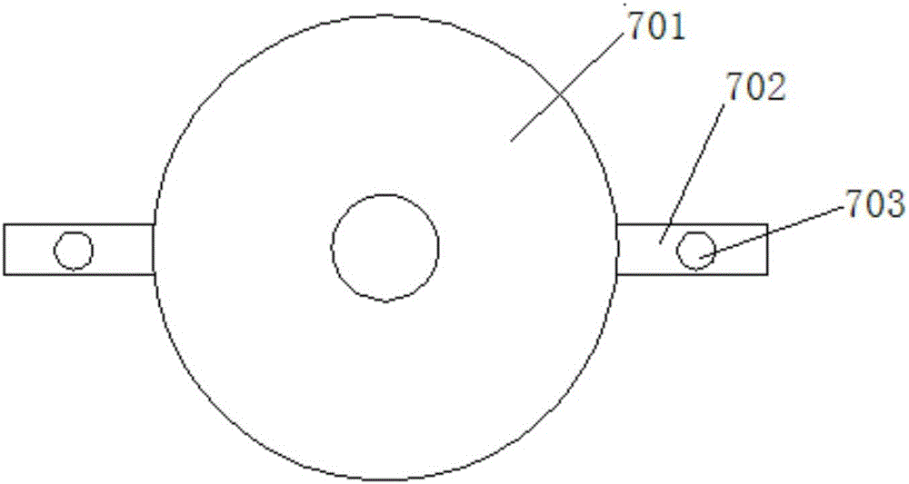
[0013] See attached figure 1 And attached figure 2 , a stirring device, comprising a lifting motor 1, a lifting column 2, a beam 3, a rotating motor 4, a stirring shaft 5, a spiral blade 6, a stirring plate 7 and a stirring tank 8, the lifting motor 1 is connected with the lifting column 2, and the lifting The lower end of the column 2 is installed on the fixed base 9, and the upper end is fixed on the beam 3. One end of the beam 3 is vertically provided with a stirring shaft 5, the stirring shaft 5 is connected with the rotating motor 4, and the bottom of the stirring shaft 5 is provided with a spiral blade 6. The bottom end of the shaft 5 is provided with a stirring plate 7, and the stirring plate 7 includes a circular disc body 701, and a stirring block 702 is arranged around the circular disc body 701, and a stirring piece 703 is installed on ...


PUM


Abstract

The invention discloses a stirring device, which comprises a lifting motor, a lifting upright post, a beam, a rotation motor, a stirring shaft, a spiral blade, a stirring disc and a stirring tank, wherein the lifting motor is connected with the lifting upright post, the lower end of the lifting upright post is installed on a fixed base, the upper end of the lifting upright post is fixed on the beam, one end of the beam is vertically provided with the stirring shaft, the stirring shaft is connected with the rotation motor, the spiral blade is arranged below the stirring shaft, the stirring disc is arranged at the bottom end of the stirring shaft and comprises a round disc body, stirring blocks are arranged at the periphery of the round disc body, stirring sheets are arranged at the upper part and the lower part of each stirring block, the spiral blade and the stirring disc are arranged in the stirring tank, an outer jacket is arranged at the outer side of the stirring tank in a sleeving manner, a spiral tube is arranged in the outer jacket, a water inlet is formed in the bottom end of the spiral tube and a water outlet is formed in the top end of the spiral tube. The stirring device has high stirring efficiency, ensures that the internal temperature of the stirring tank is not increased after long-time working, and guarantees the quality of a rubber seals.

Description

technical field [0001] The invention relates to the technical field of production equipment for rubber seals, in particular to a stirring device for producing rubber seals. Background technique [0002] In the production process of rubber seals, it is first necessary to mix a variety of raw materials evenly, and then make rubber strips. In the original mixing process, a mixing and stirring device is required. The stirring shaft of the stirring device currently used cannot be lifted up and down, and the stirring efficiency is low. There is a dead angle at the bottom of the stirring tank during work, and the stirring is uneven, and the effect is not ideal. In addition, the rubber will generate heat during the stirring process. Heat loss will affect the production quality of rubber seals, and ultimately affect the use of rubber seals. Contents of the invention [0003] The purpose of the present invention is to provide a stirring device, which has high stirring efficiency, r...

Claims


Application Information

Patent Timeline
Patent Type & Authority Applications(China)
IPC IPC(8): B01F7/16B01F15/06
CPCB01F27/192B01F27/806B01F2035/98B01F35/92B01F2101/2805
Inventor 何颜鹏
Owner TONGLING BAIRUI EQUIP PARTS CO LTD
Why Eureka
Try Eureka