Liquid nitrogen cylinder, cryogenic vial storing and fetching device and liquid nitrogen cylinder storing and fetching system

An access device and liquid nitrogen tank technology, applied in the field of liquid nitrogen tanks, can solve the problems of destroying the activity of biological samples, hidden dangers to operator safety, and high error rate, and achieve high efficiency in the picking process, avoid hidden safety hazards, and reduce workload. Effect

Active Publication Date: 2016-08-17
SHANGHAI ORIGINCELL BIOLOGICAL CRYO EQUIP CO LTD
View PDF8 Cites 76 Cited by
  • Summary
  • Abstract
  • Description
  • Claims
  • Application Information

AI Technical Summary

Problems solved by technology

[0003] At present, the liquid nitrogen storage tank is a manual structure. When selecting cryotubes, the operator needs to open the tank cover and reach into the tank to select the target cryotube. Since there are often many cryotubes stored in a liquid nitrogen tank, manual selection Tubes need to spend more time, and the opening of the liquid nitrogen tank of prior art must be big enough, just can be convenient to pick tube manually
In this way, during the tube picking process, all the cryotubes in the liquid nitrogen tank are exposed to air temperature for a long time, which is extremely harmful to biological samples, and the activity of biological samples may even be destroyed by repeated operations.
In addition, the efficiency of manual pipe picking operation is very low, and the error rate is also high
Moreover, because the temperature of the liquid nitrogen tank and the freezing tube is extremely low, manual picking of the tube poses a great safety hazard to the operator

Method used


Image

  • Liquid nitrogen cylinder, cryogenic vial storing and fetching device and liquid nitrogen cylinder storing and fetching system
  • Liquid nitrogen cylinder, cryogenic vial storing and fetching device and liquid nitrogen cylinder storing and fetching system
  • Liquid nitrogen cylinder, cryogenic vial storing and fetching device and liquid nitrogen cylinder storing and fetching system

Examples


Embodiment 1

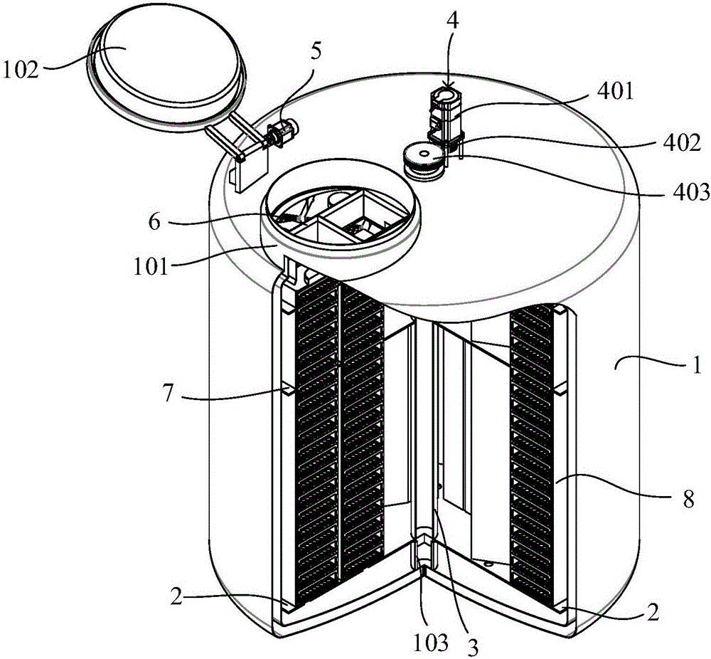
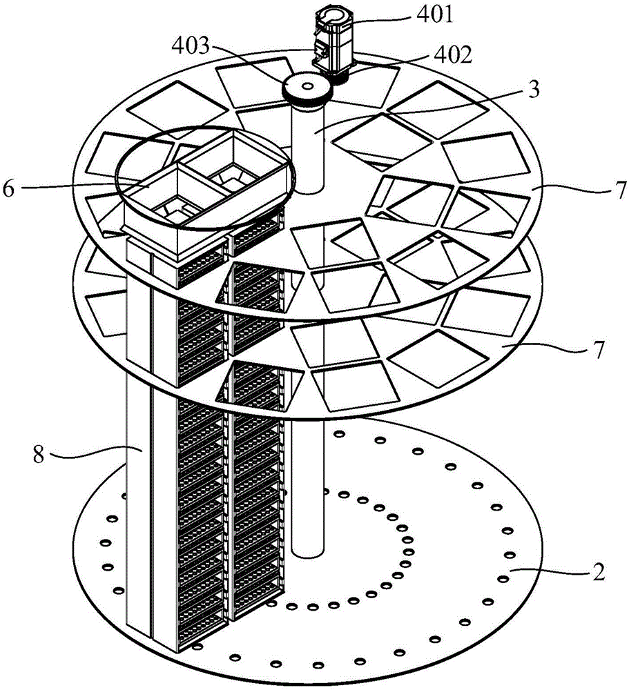
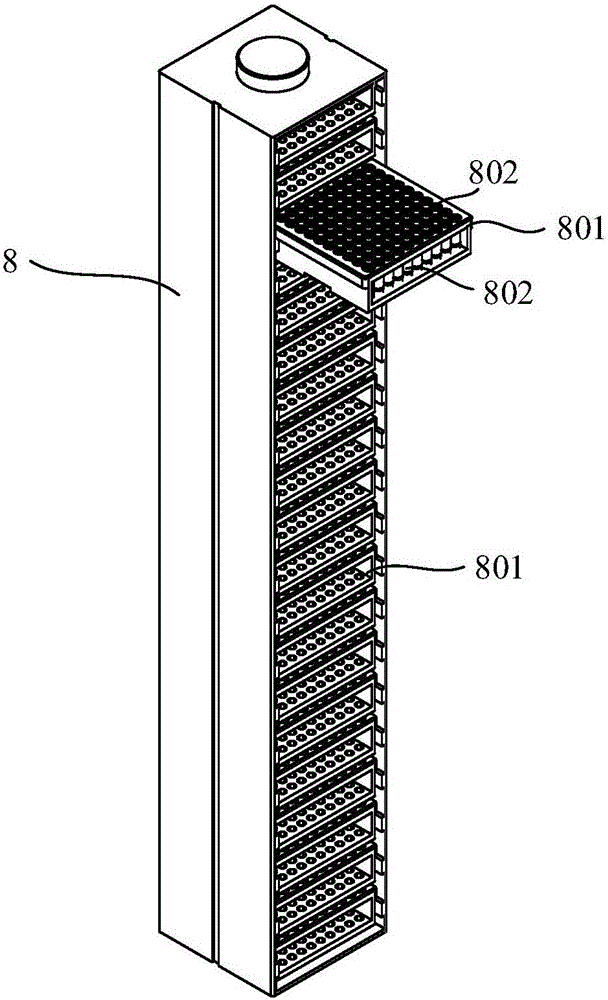
[0062] Figure 1-2 A liquid nitrogen tank is shown, including a tank body 1 , a tray 2 , a central shaft 3 and a drive assembly 4 . The lowest internal temperature of the liquid nitrogen tank can reach -196°C, and the temperature difference with the ambient temperature is very large, so the tank body 1 is generally a double-layer vacuum structure. In order to meet the requirements of material stress, the tank body 1 is designed to be arc-shaped up and down in this embodiment. The cylinder has a double-layer vacuum structure, the inner bottom of the tank body 1 is a liquid nitrogen layer, and the upper layer of the liquid nitrogen layer is a tray 2. Cryopreservation basket 8 is erected on the tray 2, such as image 3 As shown, the cryopreservation tubes 802 are arranged in an array on the cryopreservation tray 801 , and the cryopreservation trays 801 are arranged in a row and placed in the cryopreservation basket 8 . The central axis 3 is arranged vertically to the tray 2 and...

Embodiment 2

[0069] Figure 4-7 A cryotube access device is shown, which includes a housing 9, a cryotube access assembly and a docking port 901 capable of docking with an opening of a liquid nitrogen tank. In this embodiment, the liquid nitrogen tank can be a liquid nitrogen tank of the prior art. At this time, the tray needs to be manually rotated so that the target cryopreservation basket is located at the opening of the liquid nitrogen tank; the liquid nitrogen tank can also be the liquid nitrogen tank in Embodiment 1. For the nitrogen tank, there is no need to manually rotate the tray at this time, and the liquid nitrogen tank described below will be described by taking the liquid nitrogen tank in Example 1 as an example. The shell 9 of the cryopreservation tube access device is an insulated shell, and in order to ensure that the cryopreservation tube is not exposed to the external environment during extraction, such as Figure 5 As shown, the opening 101 of the liquid nitrogen tank ...

Embodiment 3

[0082] Figure 8 A storage system for a liquid nitrogen tank is shown, and the storage system for a liquid nitrogen tank includes the liquid nitrogen tank in Embodiment 1, the cryotube access device in Embodiment 2, two mobile consoles 21, and a controller (not shown in the figure). shown) and track 22. The liquid nitrogen tanks are arranged in a row in a straight line and are located on the track 22. The two mobile consoles 21 are electrically connected to the controller, and one end of the two mobile consoles 21 is respectively arranged on both sides of a liquid nitrogen tank, and the other end is arranged on the On the track 22, the mobile operating platform 21 is used for docking or disengaging the cryotube access device and the liquid nitrogen tank. A photoelectric switch (not shown) is provided at the position of each liquid nitrogen tank on the track 22, and the photoelectric switch is used to monitor the moving position of the mobile operation platform 21.

[0083] I...


PUM


Abstract

The invention discloses a liquid nitrogen cylinder, a cryogenic vial storing and fetching device and a liquid nitrogen cylinder storing and fetching system. The liquid nitrogen cylinder comprises a cylinder body, wherein the cylinder body is provided with a sealed opening; the liquid nitrogen cylinder further comprises a bracket tray; the bracket tray is arranged in the cylinder body; the bracket tray is used for bearing cryogenic baskets; a central shaft is vertical to the bracket tray and is fixedly connected with the bracket tray; a driving component is electrically connected with the central shaft; the driving component is used for driving the central shaft to rotate; and the central shaft is used for driving the cryogenic baskets to rotate through the bracket tray and conveying the cryogenic baskets to the opening. By adopting the liquid nitrogen cylinder, the error rate of manual cryogenic vial selecting is reduced; and meanwhile, safety hazards for operation personnel during a manual bracket tray rotation process are avoided. By adopting the cryogenic vial storing and fetching device, the process for selecting a single target cryogenic vial for biological samples is realized; and during the whole selecting process, the cryogenic vials are all in a liquid nitrogen environment, so that non-target cryogenic vials are prevented from being exposed at environment temperature. The liquid nitrogen cylinder storing and fetching system is applicable to vial picking work for large biological sample banks.

Description

technical field [0001] The invention relates to a liquid nitrogen tank, a freezing tube access device and a liquid nitrogen tank access system. Background technique [0002] The deep cryogenic biological sample bank is an important basic equipment for research in the fields of medicine and biology. The low temperature storage of liquid nitrogen can keep biological tissues such as blood, stem cells and immune cells alive for a long time. [0003] At present, the liquid nitrogen storage tank is a manual structure. When selecting cryotubes, the operator needs to open the tank cover, reach into the tank body and select the target cryotubes. Since there are often many cryotubes stored in a liquid nitrogen tank, manual selection Pipe then needs to spend more time, and the opening of the liquid nitrogen tank of prior art must be big enough, just can be convenient to pick pipe manually. In this way, during the tube picking process, all the cryotubes in the liquid nitrogen tank will...

Claims


Application Information

Patent Timeline
Patent Type & Authority Applications(China)
IPC IPC(8): B65D81/20B65D90/00B65G47/92B65G47/91B65G43/08A01N1/02
CPCA01N1/0252B65D81/2069B65D90/004B65G43/08B65G47/91B65G47/92
Inventor 瞿建国罗沉
Owner SHANGHAI ORIGINCELL BIOLOGICAL CRYO EQUIP CO LTD
Why Eureka
Try Eureka