Eureka AIR delivers breakthrough ideas for toughest innovation challenges, trusted by R&D personnel around the world.

Revetment diversion method for high-frequency debris flow

A mud-rock flow and high-frequency technology, applied in the direction of pier, quay wall, embankment, etc., can solve the problems of structural damage, affecting the effectiveness of prevention and control engineering, and the difficulty of determining the buried depth of the foundation in the protection mode, so as to achieve the goal of light material, fast protection, and fast The effect of protecting the ditch bank

Active Publication Date: 2016-08-17
INST OF EXPLORATION TECH OF CHINESE ACAD OF GEOLOGICAL SCI +1
View PDF5 Cites 4 Cited by
  • Summary
  • Abstract
  • Description
  • Claims
  • Application Information

AI Technical Summary

Problems solved by technology

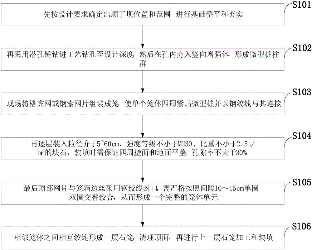
[0004] The object of the present invention is to provide a kind of high-frequency debris flow revetment diversion method, aims to solve traditional debris flow ditch bank protection and diversion engineering, and it is difficult to determine the effective foundation buried depth in the protection mode of hydraulic channel (or river course). And it cannot adapt to the change of terrain conditions during operation, and it is easy to cause structural damage under the erosion of debris flow, which seriously affects the effectiveness of the prevention and control project.

Method used


Image

  • Revetment diversion method for high-frequency debris flow
  • Revetment diversion method for high-frequency debris flow
  • Revetment diversion method for high-frequency debris flow

Examples


Embodiment example

[0026] The longitudinal slope of a gully bed in a debris flow circulation area is about 200‰, and the gully bed is rich in deposits. The material composition is crushed rocks and silty clay, and the content of crushed rocks accounts for about 20-30%. It can reach 3.0m. Under the scouring of water flow and debris flow, the gully bed cuts down strongly, and the gully is in a "V" shape; the bank slope is made of landslide debris accumulation, with a slope of 15-70°, and there are 5 residential houses on the left side of the bank slope , 1 substation and a 200-meter-long third-class road; the ditch is located in the earthquake-affected area, and debris flows have occurred on average 3 times a year in recent years. Due to the limitations of construction conditions such as terrain and construction period, it is preferred to adopt the bank revetment diversion method of the present invention for protection, and the steps are as follows:

[0027] When a debris flow breaks out in the fl...


PUM

PropertyMeasurementUnit
Particle sizeaaaaaaaaaa
Proportionaaaaaaaaaa

Abstract

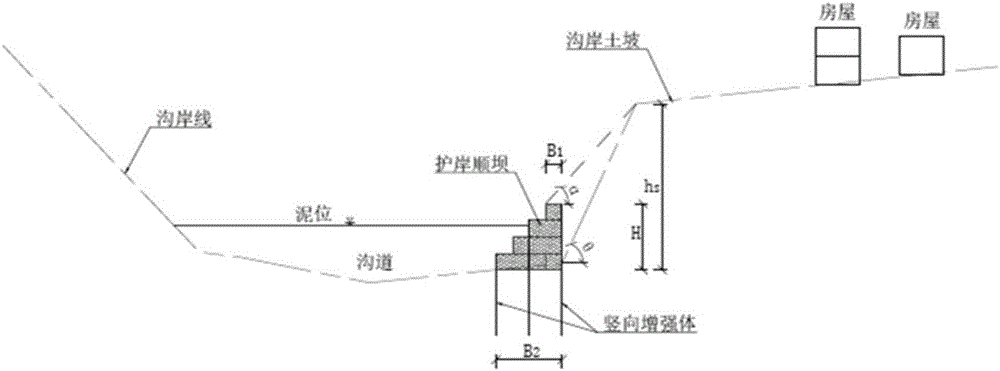
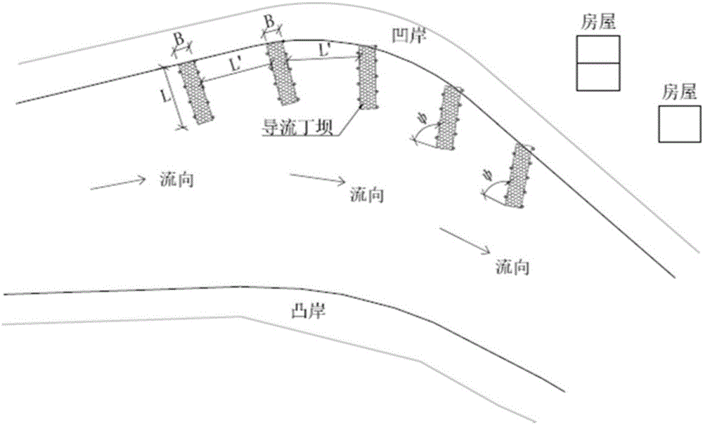
The invention discloses a revetment diversion method for a high-frequency debris flow. In the revetment diversion method, stacked gabions and vertical reinforcements deeply planted in a gully bed are comprised, and the gabions and the vertical reinforcements are mutually fused to form flexible longitudinal dikes or spur dikes; the flexible longitudinal dikes are arranged in parallel to a flow direction and along a gully bank; the spur dikes stretch into a gully centre and are arranged at an acute angle with the flow direction; the vertical reinforcements are made of micro steel pipe piles or H-shaped steel or rood piles which are arrayed and distributed in a close-triangle shape and along the axial direction of the longitudinal dikes, and are connected with the gabions by virtue of steel strands, and lower burying depths are determined by an erosion depth of the debris flow; and each adjacent spur dikes are distributed at a gully side along the flow direction at a certain interval to form a spur dike group for revetment diversion. The revetment diversion method disclosed by the invention is fast to construct, and high in erosion resistance and geography adaptability; local materials can be used, thus the construction cost is remarkably reduced; the threat of the debris flow on a loose gully bank and gully side protection object is rapidly reduced; and the revetment diversion method is suitable for emergency rescue and safety flood protection working for the high-frequency debris flow in the loosely-piled gully bank and gully side protection object.

Description

technical field [0001] The invention belongs to the technical field of natural disaster prevention, and in particular relates to a high-frequency debris flow bank protection diversion method. Background technique [0002] Debris flow is one of the common types of geological disasters in the flood season in my country, and it is widely developed in the western region of China, especially in the southwest mountainous area. Debris flow has the characteristics of sudden outbreak, strong destructive power such as erosion, and wide range of influence. It has become an important factor that seriously affects the safety of roads and other infrastructure in western mountainous areas and the economic development of urban and rural areas. At present, the situation of disaster prevention and mitigation of debris flow is still severe, especially the high-frequency debris flow in loose mountains in the earthquake area (multiple outbreaks in a flood season) highlights its importance. At p...

Claims


Application Information

Patent Timeline
IPC IPC(8): E02B3/06E02B3/12
CPCE02B3/06E02B3/129
Inventor 杨东旭黄海石胜伟游勇陈晓清刘建康杨顺
Owner INST OF EXPLORATION TECH OF CHINESE ACAD OF GEOLOGICAL SCI
Why Eureka
Eureka Blog
Learn More