Soft foundation water cover type integrated well point plastic strip vacuum system

A vacuum system and soft soil foundation technology, applied in soil protection, infrastructure engineering, construction, etc., can solve problems such as difficulty in finding air leaks, fast transmission loss, poor sealing effect, etc., and achieve the goal of reducing post-construction settlement Effect

Active Publication Date: 2016-08-17
CABR FOUND ENG CO LTD
View PDF10 Cites 4 Cited by
  • Summary
  • Abstract
  • Description
  • Claims
  • Application Information

AI Technical Summary

Problems solved by technology

[0004] 1. The construction of large-area sealing membranes is difficult, and vacuum preloading on land requires a lot of manual laying of membranes with a low degree of mechanization, especially the construction of underwater vacuum preloading sealing membranes is more difficult;
[0005] 2. The PVC sealing film has low strength and is easy to damage and leak air. The cost of the second layer of sealing film and the first layer of geotextile is high, it is difficult to find the leak point, and the sealing effect is not good;
[0006] 3. A large number of PVC sealing films are not environmentally friendly;
[0007] 4. The surface under the film can reach a maximum negative pressure of 80kPa, and the negative pressure transmission loss to the deep part of the soil layer is fast. Generally, the loss of negative pressure per meter to the deep part is about 10kPa. The effective reinforcement depth is shallow;
[0008] 5. The loading surface is on the original ground surface or the backfilled land surface. Even if the surface sealing film does not leak, the slow air leakage of the shallow soil around the reinforcement area cannot be ignored, especially in the case of long-term loading for about 90 days, when the groundwater level drops to The degree of air leakage in shallow soil around a certain degree of reinforcement area is even more worrying
[0009] 2. The improved vacuum preloading reinforcement has the following disadvantages:
[0010] 1. The sand-removing cushion layer is changed to the mode of direct connection of plastic slabs with hand-shaped joints, and the mode of indirect negative pressure transmission is changed to direct negative pressure transmission mode, but it still needs a sealing film, and the maximum negative pressure loading surface is still on the surface;
[0011] 2. The sealing layer is formed by blowing and filling mud, or the vacuum branch pipe is directly connected to the plastic discharge into the soil for about 1.5 meters, or the vacuum filter tube is about 3 meters underground, and the side blister row replaces the sealing film. The dredging fill mud loses water, consolidates and cracks, the groundwater level drops rapidly, and the sealing effect is greatly reduced;
[0012] 3. The ultra-soft soil for land reclamation cannot be mechanically constructed. First, artificially insert the shallow layer of plastic drainage vacuum preloading, and then do deep vacuum preloading after the foundation strength is suitable for mechanical construction. The principle and process of conventional vacuum preloading are almost the same, only the simple difference between manual and mechanical, the process is more complicated, the cost is high, and the efficiency is low;
[0018] For traditional main pipes and branch pipes, submersible pump gravity dewatering is used for tube wells, and a combination of submersible pump gravity dewatering and vacuum dewatering is used for deep well dewatering. The spacing between well points is larger, generally 15*15m. The coarse and sparse treatment method focuses on precipitation. If the spacing is too large and the time is short, it cannot simultaneously have the effect of vacuum preloading and negative pressure consolidation;
[0019] Coarse and sparse distribution of genetic precipitation and short-term (about 30 days) treatment methods in the precipitation dynamic compaction treatment are only suitable for shallow treatment;

Method used


Image

  • Soft foundation water cover type integrated well point plastic strip vacuum system
  • Soft foundation water cover type integrated well point plastic strip vacuum system
  • Soft foundation water cover type integrated well point plastic strip vacuum system

Examples


Embodiment 1

[0113] Basic information before foundation treatment:

[0114] The third layer of muddy clay layer of the foundation has a water content of 55%, a compressive modulus of 2.3MPa, an average layer thickness of 15 meters, a buried depth of 5 meters at the top of the layer, and a buried depth of 20 meters at the bottom.

[0115] Implementation steps:

[0116] Step 1. The site is leveled, and drainage ditches are excavated around the area to be reinforced;

[0117] Step 2. Pre-tamping, energy level 800kN.m, square tamping point spacing 4m*4m, after tamping, construct cement mixing pile lateral sealing retaining wall or mud lateral sealing retaining wall;

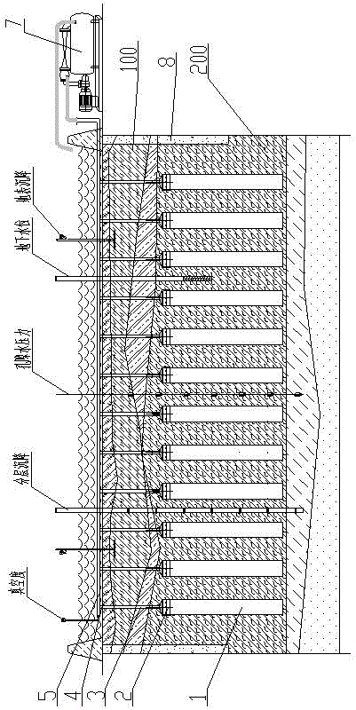
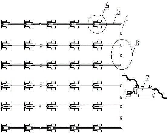
[0118] Step 3. Arrangement of integrated well point plastic exhaust vacuum system

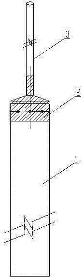
[0119] 3.1. The integrated well point plastic pipe is inserted and constructed to form an integrated well point plastic pipe grid;

[0120] The grid spacing of the integrated well point plastic pipe grid is 1.2m, and the insertion depth of the ...

Embodiment 2

[0137] Basic information before foundation treatment

[0138] The fourth silty clay layer of the foundation has a water content of 38%, a compressive modulus of 3.8 MPa, an average thickness of 13 meters, a buried depth of 3 meters at the top of the layer, and a buried depth of 16 meters at the bottom of the layer.

[0139] Step 1. The site is leveled, and drainage ditches are excavated around the area to be reinforced;

[0140] Step 2. Do not carry out pre-tamping before precipitation, and construct lateral sealing retaining wall of cement mixing pile or lateral sealing retaining wall of mud;

[0141] Step 3. Arrangement of integrated well point plastic exhaust vacuum system

[0142] 3.1. The integrated well point plastic pipe is inserted and constructed to form an integrated well point plastic pipe grid;

[0143] The grid spacing of the integrated well point plastic pipe grid is 1.5m, and the insertion depth of the integrated well point pipe is 16m

[0144] The length of ...

Embodiment 3

[0160] Basic information before foundation treatment

[0161] The silty clay in the second layer of the foundation has a water content of 78%, a compressive modulus of 2.1 MPa, an average thickness of 20 meters, a buried depth of 4 meters at the top of the layer, and a buried depth of 24 meters at the bottom of the layer.

[0162] Step 1. The site is leveled, and drainage ditches are excavated around the reinforcement area;

[0163] Step 2. Pre-tamping before precipitation, energy level 600kN.m, square tamping point spacing 4m*7m, after tamping, construct cement mixing pile lateral sealing retaining wall or mud lateral sealing retaining wall;

[0164] Step 3. Arrangement of integrated well point plastic exhaust vacuum system

[0165] 3.1. The integrated well point plastic pipe is inserted and constructed to form an integrated well point plastic pipe grid;

[0166] The grid spacing of the integrated well point plastic pipe grid is 1.0m, and the insertion depth of the integrat...


PUM


Abstract

The invention relates to a soft foundation water cover type integrated well point plastic strip vacuum system. The vacuum system is characterized by comprising an integrated well point plastic strip pipe grid formed through insertion and construction of integrated well point plastic strip pipes, wherein the integrated well point plastic strip pipes include draining plates, connecting boxes, well point pipes and connecting pipes, the draining plates are vertically distributed in a deep soil body, the well point pipes are distributed in a shallow soil body, the upper ends of the draining plates are connected with the lower ends of the well point pipes through the connecting boxes, the upper ends of the well point pipes are exposed outside the shallow soil body, and the upper ends of the well point pipes are connected with one ends of the connecting pipes; and the integrated well point plastic strip pipe grid is connected with a main pipe and a vacuum pump to form the integrated well point plastic strip vacuum system, and a water cover layer is arranged on surface of a to-be-reinforced region for distributing the integrated well point plastic strip pipe grid. The vacuum system has the advantages that the operation is simple, the cost is low, and the construction effect is good.

Description

technical field [0001] The invention relates to a method for treating soft ground, in particular to a water-covered integrated well point plastic drainage vacuum system for soft ground. Background technique [0002] According to 7.1.1 of the "Code for Design of Building Foundations" (GB5007-2011), weak foundations refer to foundations mainly composed of silt, muddy soil, flushing soil, miscellaneous filling soil or other highly compressive soil layers. Before building construction on the weak foundation, it is necessary to consolidate the weak foundation first. The conventional consolidation treatment methods are as follows: [0003] 1. Conventional vacuum preloading reinforcement. Conventional vacuum preloading reinforcement "on land and under water in rivers, seas, lakes and swamps" soft soil foundations all need to be laid with sealing film and sand cushion, but there are the following disadvantages: [0004] 1. The construction of large-area sealing membranes is difficu...

Claims


Application Information

Patent Timeline
Patent Type & Authority Applications(China)
IPC IPC(8): E02D3/10
CPCE02D3/10E02D3/103E02D2250/0053
Inventor 张禹
Owner CABR FOUND ENG CO LTD
Why Eureka
Try Eureka