
X-shaped anti-floating uplift pile

An uplift-resistant pile and pile body technology, applied in sheet pile walls, protection devices, buildings, etc., can solve the problems of the pile bottom sediment cleaning, the difficulty of monitoring the judgment of the bearing layer, the integrity of the pile body, and the large deformation after construction. Achieve the effect of expanding the anti-floating area, reducing the length and cross-sectional area, and reducing the overall cost

Inactive Publication Date: 2016-08-17
CHINA RAILWAY TUNNEL SURVEY & DESIGN INST
View PDF7 Cites 0 Cited by
  • Summary
  • Abstract
  • Description
  • Claims
  • Application Information

AI Technical Summary

Problems solved by technology

[0003] There are many kinds of pile foundation technologies. In the early days, cement-soil mixing piles, sand-stone piles, and wooden piles were mostly used. At present, they are rarely used. First, the control and management automation system of cement-soil mixing piles such as water-cement ratio, slurry volume, and mixing times is not perfect. , the equipment is outdated, the technology is backward, and there are problems of poor mixing uniformity and unstable pile quality; the second is that sand and stone piles are used to reinforce deep silt soft soil foundations. Due to the problems of long construction period and large deformation after construction, they are no longer used. It is used for building foundation treatment that requires deformation; third, wooden pile foundations have been banned for civil buildings
[0004] Cast-in-situ piles can also be used to treat the foundation with thicker silt layers. The piles are driven to the hard soil layer and used as bearing platforms. First, there is the integrity problem of the pile body in the deep soft soil of the immersed tube pile; the second is the mud pollution problem of the punching bored pile, the quality of the concrete pouring of the pile body, the cleaning of the sediment at the bottom of the pile and the difficulty in monitoring the bearing layer judgment, etc. , it is prone to uneven subsidence of civil buildings based on cast-in-place piles, resulting in wall cracks, which are caused by the above-mentioned technical problems in construction

Method used


Image

  • X-shaped anti-floating uplift pile
  • X-shaped anti-floating uplift pile
  • X-shaped anti-floating uplift pile

Examples


Embodiment 1

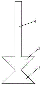
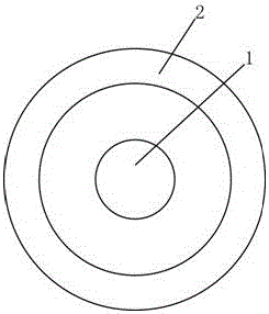
[0030] Such as Figure 1-3 As shown, an X-type anti-floating and anti-lift pile includes a pile body 1, the pile body 1 is cylindrical, and the pile body 1 extends to the outside of the pile body 1 to form a first circular cone with the pile body 1 as the rotation axis and no bottom surface body 2, the second cone body 3, the first cone body 2 is located above the second cone body 3 and the apex angles of the two are connected, the first cone body 2, the second cone body 3 along the pile body 1 The plane where the central axis is located is an X-shaped cross-sectional plane.

[0031] The first cone body 2 and the second cone body 3 have the same size.

[0032] The first conical body 2 and the second conical body 3 are located at the bottom of the pile body 1 .

[0033] Such as Figure 4-7 As shown, the specific construction process is as follows: (1) The construction sequence is to make a cylindrical hole 4 according to the rotary grouting pile process; (2) When the pile fo...

Embodiment 2

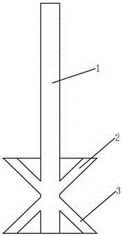
[0035] Such as image 3 , 8 As shown in and 9, an X-type anti-floating and uplift pile includes a pile body 1, the pile body 1 is cylindrical, and the pile body 1 extends to the outside of the pile body 1 to form a first shaft with the pile body 1 as the rotation axis and no bottom surface. Cone 2, the second cone 3, the first cone 2 is located above the second cone 3 and the apex angles of the two meet, the first cone 2, the second cone 3 along the The plane where the central axis of the pile body 1 is located is an X-shape after being sectioned.

[0036] The first cone body 2 and the second cone body 3 have the same size.

[0037] The first conical body 2 and the second conical body 3 are located in the middle of the pile body 1 .

[0038] Such as Figure 10-13 As shown, the specific construction process is as follows: (1) The construction sequence follows the cylindrical hole 4 of the rotary grouting pile process; (2) In the middle of the pile foundation, the drilling r...

Embodiment 3

[0040] Such as image 3 , 14 15, an X-type anti-floating and uplift pile includes a pile body 1. The pile body 1 is cylindrical. Cone 2, the second cone 3, the first cone 2 is located above the second cone 3 and the apex angles of the two meet, the first cone 2, the second cone 3 along the The plane where the central axis of the pile body 1 is located is an X-shape after being sectioned.

[0041] The first cone body 2 and the second cone body 3 have the same size.

[0042] The first conical body 2 and the second conical body 3 are located on the top of the pile body 1 .

[0043] Such as Figure 16-19 As shown, the specific construction process is as follows: (1) The construction sequence is to make a cylindrical hole 4 according to the rotary grouting pile process; (2) When the pile foundation is close to the top, the drilling rig extends out the oblique rotary drill to make a tapered hole 5; (3 ) The drilling rig is lifted up for a certain distance, and the reverse rotar...


PUM


Abstract

The invention belongs to the field of underground engineering construction, and particularly relates to an X-type anti-floating and uplift pile, which is characterized in that it includes a pile body, the pile body is cylindrical, and the pile body extends to the outside of the pile body to form a A first cone and a second cone with a rotation axis and no bottom surface, the first cone is located above the second cone and the top angles of the two are connected, the first cone, The plane where the second conical body is located along the central axis of the pile body is an X-shaped section after being sectioned. The invention expands the load-bearing area of ​​the pile. Compared with the traditional pile with the same cross-section, the load-bearing area can be increased by more than 50%, and can carry heavier loads, thereby reducing the overall cost; the anti-floating area of ​​the pile is enlarged, which effectively reduces the The floating of the pile; the bearing area is increased, and the length and cross-sectional area of ​​the pile are effectively reduced.

Description

technical field [0001] The invention belongs to the field of underground engineering construction, in particular to an X-type anti-floating and anti-lift pile. Background technique [0002] In areas with high groundwater levels in my country, especially in saturated soft soil layers with high groundwater levels or thicker silt layers, it is difficult to carry out deep treatment in large areas to construct underground works, so piling methods must be used for reinforcement, but all have to be solved. Pile structure uplift and bearing capacity issues. [0003] There are many kinds of pile foundation technologies. In the early days, cement-soil mixing piles, sand-stone piles, and wooden piles were mostly used. At present, they are rarely used. First, the control and management automation system of cement-soil mixing piles such as water-cement ratio, slurry volume, and mixing times is not perfect. , the equipment is outdated, the technology is backward, and there are problems of...

Claims


Application Information

Patent Timeline
IPC IPC(8): E02D5/44E02D31/12
CPCE02D5/44E02D31/12E02D2200/16
Inventor 徐韬周建军朱世友周金忠张笑可
Owner CHINA RAILWAY TUNNEL SURVEY & DESIGN INST
Learn More