Composite grouting stop mechanism and shield tunnel boring machine with same

A shield tunnel and composite technology, which is applied in the field of shield machines, can solve the problems of affecting slurry filling, damage to the slurry stop plate, and small support force, so as to improve work efficiency, enhance airtightness, and increase wear resistance. Effect

Inactive Publication Date: 2016-08-17
CHONGQING REINTEL SHIELD TECH
View PDF13 Cites 2 Cited by
  • Summary
  • Abstract
  • Description
  • Claims
  • Application Information

AI Technical Summary

Problems solved by technology

However, after the shield machine excavates for a period of time during use, the slurry plate will be gradually damaged due to the friction between the shield body and the soil
As a result, the grout stop plate gradually loses its airtightness, and the grout will flow to the soil bin, making it difficult to build up the grouting pressure
Because the grouting pressure cannot be established at the top of the segment, it is difficult to fill the top of the segment with grout, and the grout will flow into the soil bin along the damaged grout stop plate, thereby affecting the filling of the grout. The increase in settlement is not conducive to the waterproofing of the tunnel lining, and the damage to the slurry plate will also reduce the supporting force behind the lining of the segment, causing displacement and deformation of the segment

Method used


Image

  • Composite grouting stop mechanism and shield tunnel boring machine with same
  • Composite grouting stop mechanism and shield tunnel boring machine with same
  • Composite grouting stop mechanism and shield tunnel boring machine with same

Examples


Embodiment 1

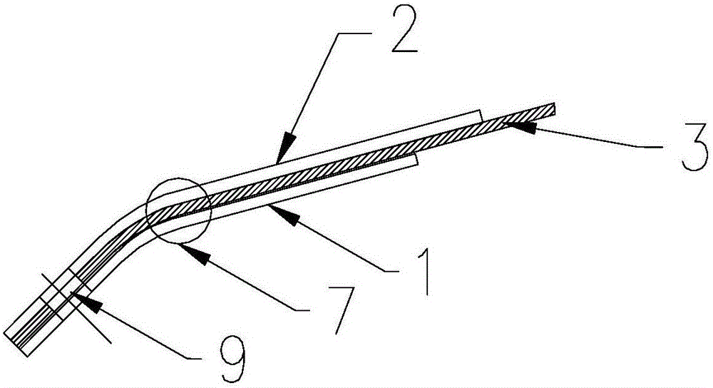
[0021] like figure 1 As shown, a composite type stopper mechanism includes a composite stopper 7, and the composite stopper 7 includes an upper stopper 2 and a lower stopper 1 arranged parallel to each other, and the upper stopper 1 A wear-resistant rubber layer 3 is arranged between 2 and the lower grout plate 1. In the present invention, the setting of the composite anti-slip plate 7 increases the wear resistance; when the upper anti-slurry plate 2 is worn, the wear-resistant rubber layer 3 compensates the worn portion of the upper anti-screw plate 2 under the action of elasticity.

Embodiment 2

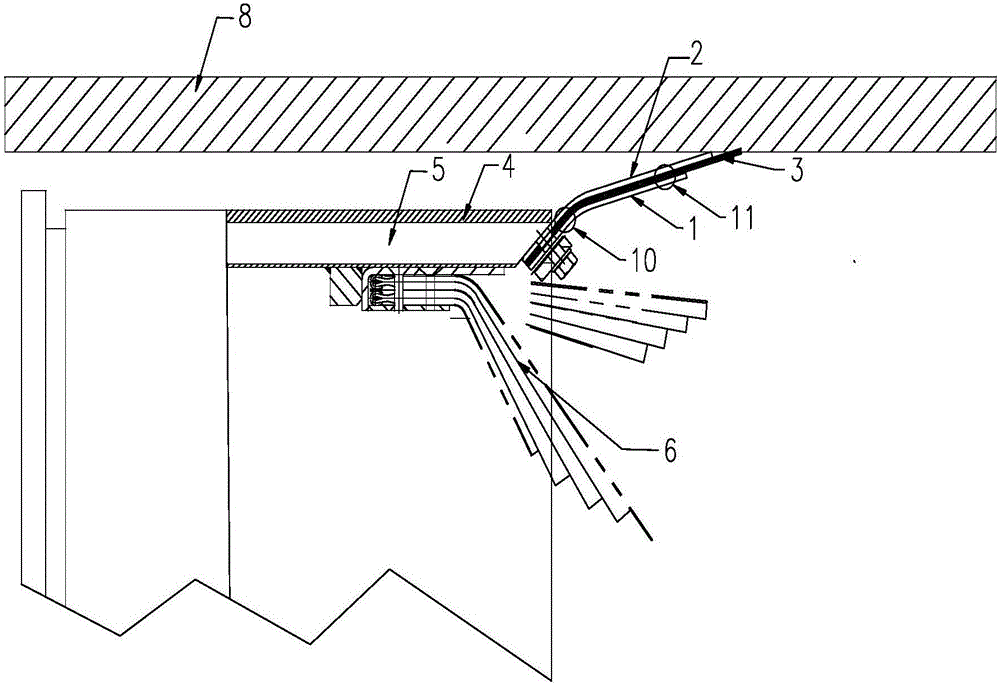
[0023] like image 3 As shown, the present invention also proposes a shield tunnel boring machine, including the composite slurry stop mechanism described in any one of claims 1-5. In the present invention, the setting of the composite anti-slip plate 7 increases the wear resistance; when the upper anti-slurry plate 2 is worn, the wear-resistant rubber layer 3 compensates the worn portion of the upper anti-screw plate 2 under the action of elasticity. Therefore, when the shield machine advances forward, the gap between the rock wall 8 and the shield tail 4 is synchronously grouted, and the composite grout stop plate 7 extends backward due to the force to form a closed space to enhance the airtightness of the grouting environment; prevent the grout from Inverting the front section of the shield will affect the construction, reduce the waste of grout, ensure the installation quality of the segments, and improve work efficiency.

[0024] When the shield machine is excavating, th...

Embodiment 3

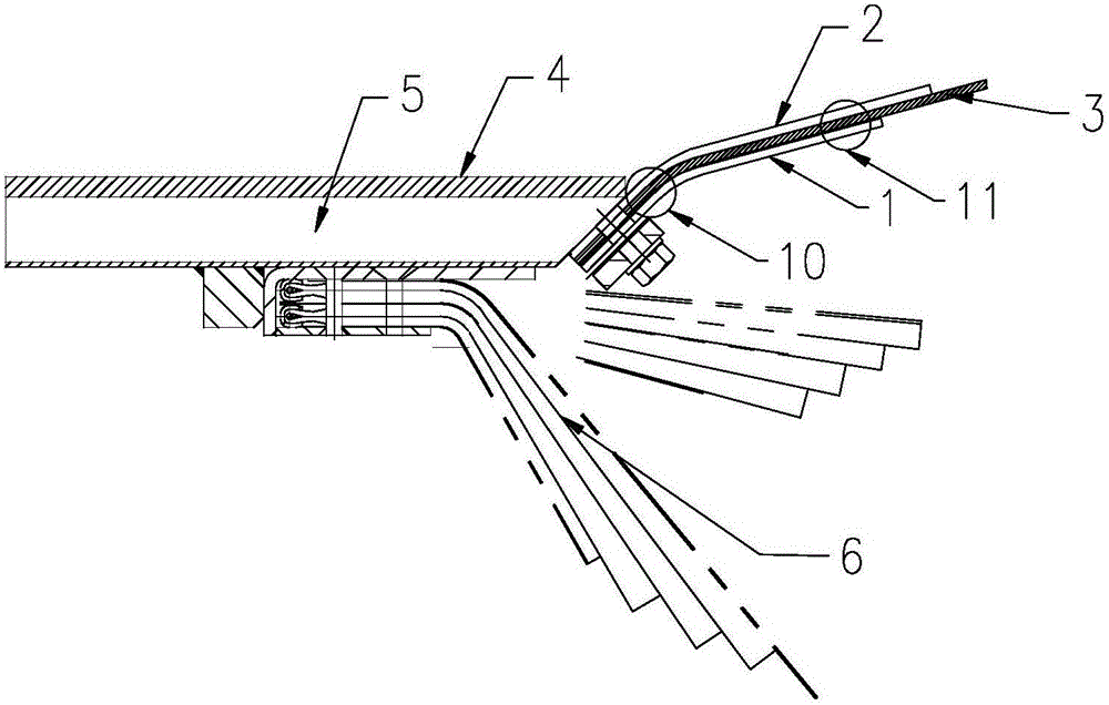
[0026] see figure 1 , figure 2 , image 3 In combination with Embodiment 1 and Embodiment 2, one end of the composite type stopper plate 7 is flush, and the flush end of the composite type stopper plate 7 is connected to the spray pipe 5 on the shield tail 4. When assembling, Put the bolts through the fixed holes 9 vertically opened on the composite type stop plate 7, and connect the flush end of the composite type stop plate 7 with the spray pipe 5 on the shield tail 4 through the bolts penetrating through the fix holes 9, wherein the spray The end surface of the pipe 5 is inclined and set at the same inclination angle as the first bending section 10 of the compound type stopper 7, so that the spray pipe 5 and the compound stopper 7 are fixedly installed without gap. The other end is set in a dislocation, and the dislocation end of the composite anti-slurry plate 7 is used to connect with the rock wall 8; wherein, the end of the wear-resistant rubber layer 3 at the end of ...


PUM


Abstract

The invention provides a composite type stopper mechanism, including a composite stopper, the composite stopper includes an upper stopper and a lower stopper arranged parallel to each other, and the upper stopper and the bottom stopper A wear-resistant rubber layer is arranged between the pulp plates. The setting of the composite type stopper increases the wear resistance; when the upper stopper is worn, the wear-resistant rubber layer compensates the worn part of the upper stopper under the action of elasticity. The present invention also proposes a shield tunnel boring machine, comprising the composite slurry stop mechanism described in any one of claims 1-5. When the shield machine advances forward, the gap between the rock wall and the shield tail is synchronously grouted, and the composite grout-stop plate extends backward due to the force to form a closed space to enhance the airtightness of the grouting environment; prevent the grout from pouring back into the front of the shield Affect the construction, reduce the waste of grout, ensure the quality of segment installation, and improve work efficiency.

Description

technical field [0001] The invention relates to the technical field of shield machines, in particular to a composite slurry stop mechanism and a shield tunnel boring machine with the slurry stop mechanism. Background technique [0002] Shield tunnel boring machine, referred to as shield machine, is a special construction machine for tunnel boring. When the shield machine is working, under the action of the thrust of the propulsion cylinder, the grouting of one ring segment is completed at the same time, and then the excavation is stopped, and the segment assembly machine completes the assembly of the next ring segment. [0003] The post-grouting of the segment arm of the shield machine can be divided into synchronous grouting, secondary reinforcement grouting and water plugging grouting according to the time of advancing the shield and the purpose of grouting. [0004] When the synchronous grouting method is adopted, that is, the synchronous grouting is through the synchron...

Claims


Application Information

Patent Timeline
Patent Type & Authority Applications(China)
IPC IPC(8): E21D11/10E21D9/06
CPCE21D11/102E21D9/06
Inventor 王彬沈熙智
Owner CHONGQING REINTEL SHIELD TECH
Why Eureka
Try Eureka