
Brake system with electric actuator

A brake system and electric push rod technology, applied in the brake field, can solve the problems of large installation size, waste of resources, complex structure, etc., and achieve the effect of increasing the range of installation size, simplifying the structure, and expanding the installation range

Inactive Publication Date: 2016-08-17
CHENGDU JINDE ZHIDONG TECH CO LTD
View PDF8 Cites 3 Cited by
  • Summary
  • Abstract
  • Description
  • Claims
  • Application Information

AI Technical Summary

Problems solved by technology

The installation size of the brake system is relatively large, the power of the motor and the model of the motor are limited, the structure is relatively complicated, and there is a lot of waste of resources

Method used


Image

  • Brake system with electric actuator
  • Brake system with electric actuator
  • Brake system with electric actuator

Examples


Embodiment Construction

[0023] In order to make the purpose, technical solutions and advantages of the embodiments of the present invention clearer, the technical solutions in the embodiments of the present invention will be clearly and completely described below in conjunction with the drawings in the embodiments of the present invention. Obviously, the described embodiments It is a part of embodiments of the present invention, but not all embodiments. The components of the embodiments of the invention generally described and illustrated in the figures herein may be arranged and designed in a variety of different configurations. Accordingly, the following detailed description of the embodiments of the invention provided in the accompanying drawings is not intended to limit the scope of the claimed invention, but merely represents selected embodiments of the invention. Based on the embodiments of the present invention, all other embodiments obtained by persons of ordinary skill in the art without cre...


PUM


Abstract

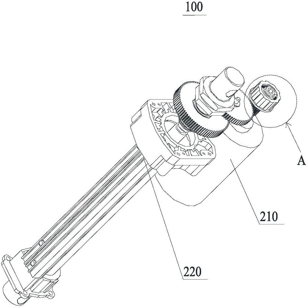
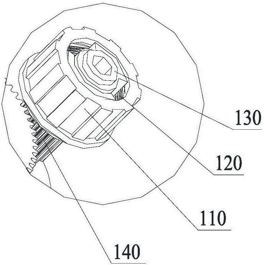
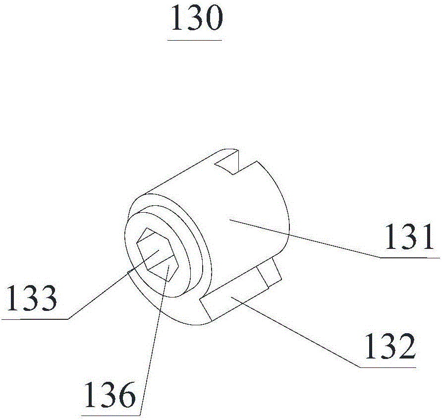
A brake system with an electric actuator comprises a driving device and a brake assembly. A coupling is arranged on an output shaft of the driving device in a sleeving manner and synchronously rotates with the output shaft. Input teeth are arranged on the output shaft in a sleeving manner. A brake torsional spring is mounted in a brake friction sleeve, and both the coupling and a brake pad are arranged in the brake torsional spring in a sleeving manner. When the coupling drives the brake pad to rotate, the brake pad drives the brake torsional spring to synchronously rotate relative to the brake friction sleeve. The output end of a transmission mechanism is connected with the input teeth. When the output end drives a first transmission gear to rotate, the brake torsional spring is stretched up by the brake pad, and the brake torsional spring is clamped in the brake friction sleeve. According to the brake system with the electric actuator, the output shaft of the driving device directly synchronously rotates with the first transmission gear through the coupling, and a speed reducing mechanism is omitted, so that mounting size range is increased, the application range and the properties of the coupling are increased, the manufacture cost can be effectively reduced, and resources are saved.

Description

technical field [0001] The invention relates to the technical field of braking, in particular to an electric push rod braking system. Background technique [0002] The motor makes the object run at high speed. When the motor is turned off, the high-speed running object cannot be stopped immediately. It needs a certain braking system to stop it, so as to achieve the purpose of moving the object from a moving state to a static state. [0003] In the braking system of the prior art, the rotation of the motor drives the rotation of the planetary double gear on the gear box, the planetary double gear drives the sun gear to rotate, the sun gear drives the transmission shaft to rotate, the transmission shaft drives the coupling to rotate, and the coupling drives the transition tooth rotation. The installation size of the brake system is relatively large, the power and model of the motor are limited, the structure is relatively complicated, and there is a lot of waste of resources....

Claims


Application Information

Patent Timeline
Patent Type & Authority Applications(China)
IPC IPC(8): F16D49/02F16D1/06H02K7/102H02K7/116
CPCF16D1/06F16D49/02H02K7/102H02K7/116
Inventor 杨勇李以舟周后科刘明
Owner CHENGDU JINDE ZHIDONG TECH CO LTD
Learn More