
High-purity ammonia filling system and filling method for high-purity ammonia

A high-purity ammonia and cooling device technology, which is applied in the container filling method, the container discharging method, and the equipment loaded into the pressure vessel, etc., can solve the problems of polluting high-purity ammonia products, avoid pollution, and reduce filling energy consumption. , The effect of convenient filling

Active Publication Date: 2018-03-20
浙江英德赛半导体材料股份有限公司
View PDF6 Cites 1 Cited by
  • Summary
  • Abstract
  • Description
  • Claims
  • Application Information

AI Technical Summary

Problems solved by technology

The traditional method of tank car filling is to use pumps to provide filling power, which takes a short time to fill, but there is a risk of polluting high-purity ammonia products

Method used


Image

  • High-purity ammonia filling system and filling method for high-purity ammonia

Examples


Embodiment 1

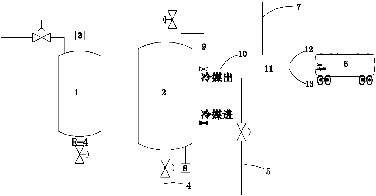
[0018] A high-purity ammonia filling system, such as figure 1 As shown, it includes a product buffer tank 1, a product tank 2 and a cooling device 10. The product buffer tank 1 is connected to the output end of the high-purity ammonia production line, and a first liquid level gauge for detecting the liquid level of the product buffer tank 1 is installed on it. 3. The liquid phase interface of the product buffer tank 1 is connected to the liquid phase interface of the product tank 2 through the first liquid phase pipeline 4, and the liquid phase interface of the tank truck 6 is connected through the second liquid phase pipeline 5 through the filling station 11. Interface connection, the gas phase interface of the product tank 2 is connected to the gas phase interface of the tank car 6 through the product tank gas phase pipeline 7 through the filling station 11, in the first liquid phase pipeline 4, the second liquid phase pipeline 5 and the gas phase pipeline 7 of the product t...

Embodiment 2

[0021] A filling method for filling high-purity ammonia using the filling system in Example 1, comprising the following steps: S1: After the tank car 6 is cleaned, the gas and liquid phase interfaces of the tank car pass through the gas phase pipeline 12 of the tank car, the tank car The liquid phase pipeline 13 of the tanker is connected to the filling station 11, and the gas phase pipeline 12 and the liquid phase pipeline 13 of the tanker are purged, maintained and vacuumed through the filling station 11; S2: the product tank 2 The internal pressure is P1 (by the cooling device 10 to reduce the temperature and pressure), keep the second liquid phase pipeline 5 cut off, open the tank car and the corresponding valve of the pipeline to make the gas phase pipeline 7 of the product tank and the gas phase pipeline 12 of the tank car conduct Thereby reducing the pressure in the tank car 6, along with the continuous operation of the cooling device 10, the pressure in the tank car 6 a...


PUM


Abstract

The invention discloses a high-purity ammonia filling system and a filling method using the filling system to fill high-purity ammonia. The filling system comprises a product buffering tank, a product tank and a cooling device, wherein the product buffering tank is connected with the output end of a high-purity ammonia production line, and a first liquid level meter is arranged on the product buffering tank; a liquid phase connector of the product buffering tank is connected with a liquid phase connector of the product tank through a first liquid phase pipeline and connected with a liquid phase connector of a tank wagon via a filling station through a second liquid phase pipeline; a gas phase connector of the product tank is connected with a gas phase connector of the tank wagon via the filling station through a gas phase pipeline of the product tank; valves used for controlling the connection and disconnection of all of the pipelines are separately arranged on the first liquid phase pipeline, the second liquid phase pipeline and the gas phase pipeline of the product tank; a second liquid level meter and a temperature sensor are arranged on the product tank; and the cooling device is used for cooling and depressurizing the product tank. By adopting the filling system and the filling method disclosed by the invention, pollution can be effectively avoided in the filling process, product purity is ensured, and filling energy consumption can be effectively reduced. The filling system and the filling method have great practicability.

Description

technical field [0001] The invention relates to a high-purity ammonia filling system and a filling method using the high-purity ammonia filling system, belonging to the technical field of high-purity ammonia filling. Background technique [0002] Electronic-grade high-purity ammonia is widely used in semiconductor lighting, flat panel display, solar cells, and large-scale integrated circuit manufacturing. The development of these emerging industries has brought new market demand for electronic-grade high-purity ammonia. At the same time, the filling technology of electronic grade high-purity ammonia faces new challenges. Currently, electronic-grade high-purity ammonia is supplied to customers in steel cylinders and tank trucks. As the demand for electronic grade high-purity ammonia increases, tank car filling will dominate. The traditional method of tank car filling is to use pumps to provide filling power, which takes a short time for filling, but there is a risk of pollu...

Claims


Application Information

Patent Timeline
Patent Type & Authority Patents(China)
IPC IPC(8): F17C5/02F17C13/00F17C13/02F17C13/04
CPCF17C5/02F17C13/00F17C13/025F17C13/026F17C13/04F17C2205/0323F17C2227/0344F17C2227/0348
Inventor 赵晓兰潘伟刘攀丁高松严巍
Owner 浙江英德赛半导体材料股份有限公司
Learn More