
A differential pulse detecting apparatus for terahertz wave time domain information and a differential pulse detecting method

A terahertz pulse and detection device technology, applied in the field of terahertz time-domain scanning, can solve the problems of limited optical path design and construction process, and restrictions on large-scale applications

Active Publication Date: 2016-08-17
UNIV OF SHANGHAI FOR SCI & TECH
View PDF6 Cites 10 Cited by
  • Summary
  • Abstract
  • Description
  • Claims
  • Application Information

AI Technical Summary

Problems solved by technology

This method can realize accurate time-domain information scanning over a long distance, but requires that the optical path difference between the pump light and the probe light must be equal to complete the time-domain information scanning, so the optical path design and construction process is extremely difficult. Large is limited by the requirements of the optical path difference; at the same time, the requirements of the entire system for the optical path difference limit the volume of the object to be detected, thus greatly limiting its large-scale application

Method used


Image

  • A differential pulse detecting apparatus for terahertz wave time domain information and a differential pulse detecting method
  • A differential pulse detecting apparatus for terahertz wave time domain information and a differential pulse detecting method
  • A differential pulse detecting apparatus for terahertz wave time domain information and a differential pulse detecting method

Examples


Embodiment Construction

[0030] The specific implementation manners of the present invention will be described below in conjunction with the accompanying drawings.

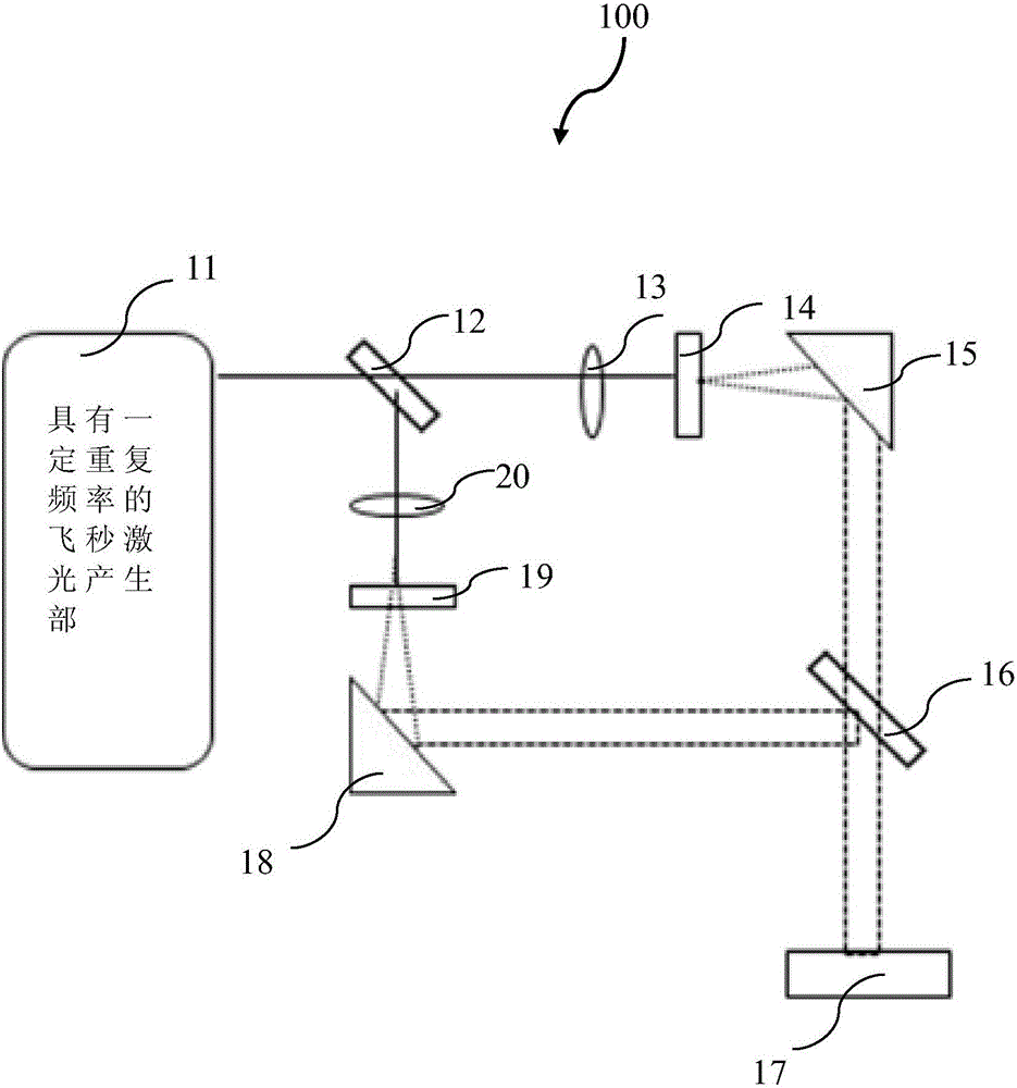
[0031] figure 1 It is a structural schematic diagram of the abnormal pulse detection device for terahertz wave time domain information in this embodiment.

[0032] Such as figure 1 As shown, the different pulse detection device 100 for terahertz wave time domain information includes a femtosecond laser generating part 11 with a certain repetition frequency, a beam splitting part 12, a convex lens 13, a semiconductor antenna 14, a parabolic mirror 15, a high-resistance silicon chip 16, The sample storage part 17, the terahertz pulse collection part 18, the detection part 19, the detection laser pulse focusing part 20, the spatial optical path length modulation part and the terahertz pulse reduction part not shown in the figure. Among them, the convex lens 13, the semiconductor antenna 14, the parabolic mirror 15, and the high-resistance ...


PUM


Abstract

A differential pulse detecting apparatus for terahertz wave time domain information and a differential pulse detecting method are provided. The apparatus includes a femtosecond laser generating unit with a certain repetition frequency, a beam splitting unit, a terahertz pulse generating unit, a unit containing a sample to be detected, a terahertz pulse collecting unit, a detecting laser pulse focusing unit, a detecting unit, a spatial light modulation unit and a terahertz pulse reduction unit. As the spatial light modulation unit can regulate the spatial optical path difference between a terahertz pulse and a detecting laser pulse, the difference between the terahertz pulse and the detecting laser pulse simultaneously reaching the detecting unit is an integral multiple of an adjacent pulse interval, and therefore the method can regulate the optical path difference in real time according to the size of a detected object under a condition that a whole optical path system is determined, a design of the overall system is not limited to the size of the detected object, and limitation of traditional terahertz time-domain spectroscopy systems on the size of the detected object is got rid of.

Description

technical field [0001] The invention belongs to the field of terahertz time-domain scanning, and in particular relates to a different-pulse detection device and a different-pulse detection method for terahertz wave time-domain information. Background technique [0002] Due to its relatively weak photon energy, terahertz waves are called the optical band for "non-destructive detection". Since the rotational and vibrational energy levels of biomolecules (ie fingerprint spectrum) are mostly in the terahertz band, photons in this band can be used to analyze and manipulate the structure of biomolecules. Therefore, terahertz waves have important application value in biomedical imaging, detection and identification of material components. But overall, research on terahertz waves in these areas is still in the laboratory stage, and large-scale applications still face many challenges. If the power of the existing terahertz radiation source is low, it will limit the penetration of t...

Claims


Application Information

Patent Timeline
Patent Type & Authority Applications(China)
IPC IPC(8): G01N21/3586
CPCG01N21/3586
Inventor 李敏殷晨晖曾和平
Owner UNIV OF SHANGHAI FOR SCI & TECH
Learn More