A fluorescent wheel thermal control device

A fluorescent wheel and thermal control technology, applied in the field of laser light sources, can solve the problem of high working temperature of the fluorescent wheel and achieve the effect of improving the utilization rate of light energy

Active Publication Date: 2017-06-23
HUBEI JIUZHIYANG INFRARED SYST CO LTD
View PDF10 Cites 0 Cited by
  • Summary
  • Abstract
  • Description
  • Claims
  • Application Information

AI Technical Summary

Problems solved by technology

[0004] The purpose of the present invention is to provide a fluorescent wheel thermal control device that can effectively solve the problem of excessively high operating temperature of the existing fluorescent wheel and help improve the overall performance of the laser light source according to the deficiencies of the prior art.

Method used


Image

  • A fluorescent wheel thermal control device
  • A fluorescent wheel thermal control device

Examples


Embodiment Construction

[0023] The present invention will be described in further detail below in conjunction with the accompanying drawings.

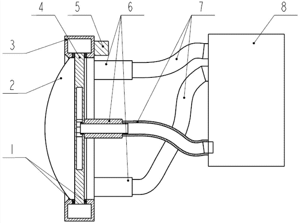
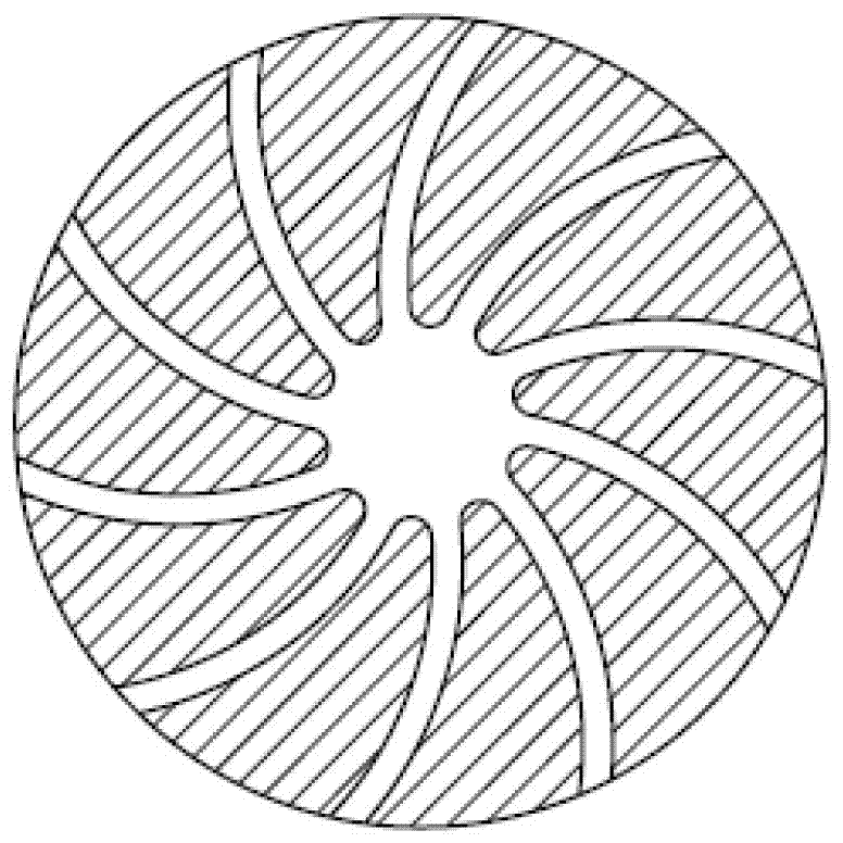
[0024] refer to figure 1 , figure 2 As shown, the present invention discloses a fluorescent wheel thermal control device, including a fluorescent wheel 4 as a supporting body and an optical lens 2 arranged on the front end of the fluorescent wheel 4, and the two mirror surfaces of the optical lens 2 are coated with a visible light anti-reflection film , the purpose of which is to increase the transmittance of blue and yellow light, and improve the light energy utilization rate of the equipment, and also includes a liquid return device 3 coated on the radial edge of the fluorescent wheel 4, which is used to collect the liquid passing through the circulation pipeline, The interior of the fluorescent wheel 4 is provided with a plurality of circulation pipelines connected with the liquid reflux device 3, the circulation pipelines are in the shape of an involute...


PUM


Abstract

The invention discloses a fluorescent wheel heat control device. The fluorescent wheel heat control device comprises a fluorescent wheel serving as a supporting body and an optical lens arranged on the front end face of the fluorescent wheel, and further comprises a liquid backflow device arranged on the peripheral surface of the fluorescent wheel in a coating mode. A plurality of circulating pipelines communicated with the liquid backflow device are arranged in the fluorescent wheel, a balance weight module is arranged on the liquid backflow device, a sealing ring is arranged between the fluorescent wheel and the liquid backflow device, universal joints are arranged on the back face of the fluorescent wheel and the liquid backflow device and connected with a liquid cooling driving module through liquid cooling pipelines, and the liquid cooling driving module comprises a liquid storage device and a driving pump used for making the whole circulating pipelines full of liquid in the liquid storage device. The fluorescent wheel heat control device is flexible in design, convenient to install, stable in performance, and capable of effectively solving the problem of too high working temperature of an existing fluorescent wheel and improving the equipment performance of a high-power projection system.

Description

technical field [0001] The invention belongs to the technical field of laser light sources, and in particular relates to a fluorescent wheel thermal control device. Background technique [0002] In recent years, with the rapid development of display technologies such as DLP, LCD, and LCOS, the projection display market has gradually expanded, and it is no longer limited to the field of theaters, but also widely covers industries such as engineering, home use, teaching, and monitoring. People's performance requirements for projection systems are also rising, especially for some high-end projection systems that use the fourth-generation new laser light source. When the laser light source is working, most of the laser light sources use blue laser light to irradiate the fluorescent wheel. After exciting yellow light, it mixes with blue light to output white light. mode. The high-power laser is irradiated on the surface of the fluorescent wheel, and the resulting high heat will ...

Claims


Application Information

Patent Timeline
Patent Type & Authority Patents(China)
IPC IPC(8): G03B21/20G03B21/16
CPCG03B21/16G03B21/204G03B21/2053
Inventor 潘海俊郭磊王源王龙崔小强
Owner HUBEI JIUZHIYANG INFRARED SYST CO LTD
Why Eureka
Try Eureka