Charging pile control system based on street lamp Internet of Things

A control system and charging pile technology, applied in the field of the Internet of Things, can solve the problems of scarce distribution of charging piles in the central area of ​​the city, long-term parking of charging piles, high administrative and construction costs, etc., to improve the charging experience and improve the comprehensive management of the city. Ability, light pole distribution wide effect

Inactive Publication Date: 2016-08-17
东莞中科智城软件有限公司
View PDF10 Cites 13 Cited by
  • Summary
  • Abstract
  • Description
  • Claims
  • Application Information

AI Technical Summary

Problems solved by technology

[0004] The existing charging pile control system is mainly jointly deployed by the charging pile enterprise and the power grid group. It mainly builds a charging station in an area on the outskirts of the city dedicated to charging electric vehicles. The charging station is far away from the commercial and living circles in the city center. The reason is that the original urban planning is relatively lagging behind. The deployment of charging piles requires long-term parking spaces, and the installation of charging piles requires digging the road to bury cables for power supply. It even needs to expand the capacity of power distribution cabinets. The administrative and construction costs are very high. High, resulting in the extremely scarce distribution of charging piles in the central area of ​​the city, making it difficult to meet the needs of users
In addition, because each charging pile terminal in the traditional charging pile control system needs to use the GPRS network to communicate with the background, the accumulated monthly communication costs are very high

Method used


Image

  • Charging pile control system based on street lamp Internet of Things
  • Charging pile control system based on street lamp Internet of Things
  • Charging pile control system based on street lamp Internet of Things

Examples


Embodiment Construction

[0024] In order to make the above objects, features and advantages of the present invention more comprehensible, the technical solutions of the present invention will be described in detail below in conjunction with the accompanying drawings and specific embodiments.

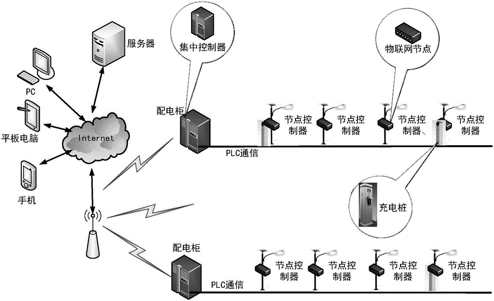
[0025] The street lamp Internet of things is mainly built for the management of urban street lamps. It has the functions of turning on and off the lights, adjusting the brightness, querying street lamp data, and fault alarms for each street lamp. Most of the smart street lamps at this stage are controlled by old street lamp systems After transformation, the original street light system has no control system and cannot perform remote control. To achieve remote control, a node controller must be installed on each street light, and it is extremely difficult to transform the existing street light lines. So the node controller uses the power line for data transmission, also called power line carrier communication. In...


PUM


Abstract

The invention discloses a charging pile control system based on a street lamp Internet of Things. The charging pile control system comprises charging piles, an Internet of Things node controller, an integrated controller, a monitoring server, an upper terminal. The charging piles are installed on light poles and connected with an interface of the Internet of Things node controller, and the integrated controller is in wireless communication with the Internet of Things node controller and the monitoring server. The Internet of Things node controller collects relevant data of the charging piles and transmits the relevant data to the integrated controller; the integrated controller transits to the monitoring server the relevant data of the charging piles transmitted by the Internet of Things node controller; the monitoring server performs analysis processing on the collected relevant data of the charging piles and transmits processing results to the upper terminal; and the upper terminal is used for enabling users to search in-place conditions of the surrounding charging piles, perform navigation to the positions of the charging piles and perform on-line payment for a charging service. The administration and construction cost and communication costs are greatly reduced.

Description

technical field [0001] The invention relates to the technical field of the Internet of Things, in particular to a charging pile control system based on the Internet of Things for street lamps. Background technique [0002] The charging pile control system is a comprehensive system integrating automatic monitoring instrument technology, computer technology and network communication technology. The system can automatically monitor the operating parameters of the electric charging piles deployed in various places, and control the charging piles to provide charging services through authorized instructions. [0003] Such as figure 1 As shown, each charging pile is equipped with a GPRS network communication module for the charging pile to communicate with the management server. The management personnel manage each charging pile through the management server. The management content includes: charging pile operation status monitoring, charging authorization Management, charge bill...

Claims


Application Information

Patent Timeline
Patent Type & Authority Applications(China)
IPC IPC(8): G05B19/418B60L11/18
CPCB60L53/31G05B19/41855Y02T10/70Y02T10/7072Y02T90/12Y02T90/16
Inventor 袁峰李引李然郭桂福叶东林黄远弘
Owner 东莞中科智城软件有限公司
Why Eureka
Try Eureka