A touch control display panel

A touch display panel, touch position technology, applied in the direction of instrument, electrical digital data processing, input/output process of data processing, etc. Thin, good optical effect, simple process effect

Active Publication Date: 2016-08-17
AU OPTRONICS CORP
View PDF4 Cites 13 Cited by
  • Summary
  • Abstract
  • Description
  • Claims
  • Application Information

AI Technical Summary

Problems solved by technology

However, the use of such an external pressure sensor not only requires an additional bonding process, but the thickness of the pressure sensor substrate is also likely to increase the thickness of the overall module, which is contrary to the current trend of thinning, and the external pressure sensor may also cause liquid crystal displays. optical quality degradation

Method used


Image

  • A touch control display panel
  • A touch control display panel
  • A touch control display panel

Examples


Embodiment Construction

[0032] The present invention will be described in detail below in conjunction with the accompanying drawings and specific embodiments, but not as a limitation of the present invention.

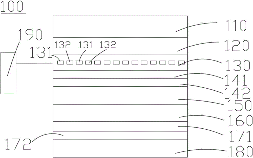
[0033] figure 1 It is a schematic diagram of an embodiment of the touch display panel of the present invention, figure 2 It is a timing diagram of an embodiment of the touch display panel of the present invention, please refer to figure 1 The touch display panel 100 includes a first electrode layer 130, a common electrode layer 160, and a control circuit 190. The first electrode layer 130 includes a plurality of first sensing electrodes 131 and a plurality of second sensing electrodes 132. The control circuit 190 is coupled to connected to the first electrode layer 130.

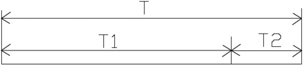
[0034] Refer again figure 2 , this embodiment is divided into the first period T1 and the second period T2 to drive the touch display panel 100 differently. In the first period T1, the control circuit 190 detects the plu...


PUM


Abstract

The invention provides a touch control display panel comprising a first electrode layer which includes a plurality of first sensing electrodes and a plurality of second sensing electrodes, a common electrode layer, and a control circuit coupled to the first electrode layer, wherein in a first period, the control circuit detects the variation of the capacitance between the first sensing electrodes and the second sensing electrodes to determine a touch control position, and in a second period, the control circuit detects the variation of the capacitance between the second sensing electrodes and the common electrode layer to determine the magnitude of touch control force of the touch control position, the first period and the second period being adjacent to each other and non-coincident. The second sensing electrodes in the first electrode layer of the touch control display panel realize time division multiplexing, being touch control sensors during touch control position detection and being pressure sensors during touch control force magnitude detection; the second sensing electrodes and the common electrode layer form a self-capacitive manner, so that cutting of the common electrode layer is not needed.

Description

technical field [0001] The present invention relates to a touch display panel, in particular to a touch display panel with pressure sensing function. Background technique [0002] The existing touch panel with integrated touch function of the liquid crystal display can only detect the touch position, but cannot detect the magnitude of the touch force. To have the function of detecting the size of the touch force, it also needs to be achieved by an external pressure sensor (force sensor). However, using this type of external pressure sensor not only requires an additional bonding process, but also the thickness of the pressure sensor substrate will easily increase the thickness of the overall module, which is contrary to the current trend of thinning, and the external pressure sensor may also cause liquid crystal displays. Optical quality deteriorates. Contents of the invention [0003] In order to solve the above technical problems of the external pressure sensor, the pr...

Claims


Application Information

Patent Timeline
Patent Type & Authority Applications(China)
IPC IPC(8): G06F3/041G06F3/044
CPCG06F3/0412G06F3/0414G06F3/044G06F2203/04112
Inventor 陈志成刘贵文
Owner AU OPTRONICS CORP
Why Eureka
Try Eureka