

Silicon schottky junction taking Bi2Se3 film as contact layer and preparation method
A Schottky junction and contact layer technology, used in electrical components, circuits, semiconductor devices, etc., can solve the problem that the quality of the heterojunction interface cannot be guaranteed, the characteristics of the silicon Schottky junction are deteriorated, and it is not suitable for large-scale production. and other problems, to achieve excellent optical and electrical properties, reduce Si surface state density, and achieve ideal properties.
- Summary
- Abstract
- Description
- Claims
- Application Information
AI Technical Summary
Problems solved by technology
Method used
Image

Examples
Embodiment 1
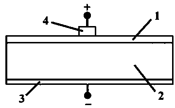
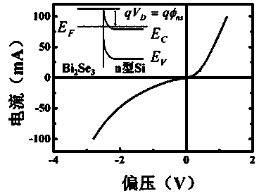
[0030] Such as figure 1 As shown, the present embodiment includes n-type Si substrate 2, the resistivity of Si substrate 2 is 0.001Ω·cm, and the top of Si substrate 2 is provided with Bi 2 Se 3 Schottky contact layer 1, Bi 2 Se 3 The thickness of Schottky contact layer 1 is 5nm, and the bottom of Si substrate 2 is provided with ohmic contact back electrode 3, Bi 2 Se 3 The Schottky contact layer 1 is provided with an ohmic contact electrode 4 made of Al with a thickness of 20nm, Bi 2 Se 3 An adhesive layer is provided between the Schottky contact layer 1 and the ohmic contact electrode 4, and the adhesive layer is made of Cr.
[0031] Preferably, the Si substrate 2 in this embodiment is a (111)-oriented single crystal.
[0032] A Bi 2 Se 3 A method for preparing a silicon Schottky junction with a thin film as a contact layer, comprising the following steps:
[0033] (a) After the Si substrate with the crystal orientation of (111) is cleaned by RCA chemical cleaning m...
Embodiment 2
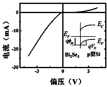
[0040] Such as figure 1 As shown, the present embodiment includes a p-type Si substrate 2, the resistivity of the Si substrate 2 is 10Ω·cm, and the top of the Si substrate 2 is provided with a thickness of 27.5nm. 2 Se 3 Schottky contact layer 1, the bottom of Si substrate 2 is provided with ohmic contact back electrode 3, Bi 2 Se 3 The Schottky contact layer 1 is provided with an ohmic contact electrode 4 made of Ag and having a thickness of 110 nm, Bi 2 Se 3 An adhesive layer is provided between the Schottky contact layer 1 and the ohmic contact electrode 4, and the adhesive layer is made of Ti.
[0041] Preferably, the Si substrate 2 in this embodiment is a (111)-oriented single crystal.
[0042] A Bi 2 Se 3 A method for preparing a silicon Schottky junction with a thin film as a contact layer, comprising the following steps:
[0043] (a) After the Si substrate with the crystal orientation of (111) is cleaned by RCA chemical cleaning method, the chemical passivation...
Embodiment 3
[0050] Such as figure 1 As shown, the present embodiment includes a type that is close to the high-resistance n-Si substrate 2 of intrinsic conductance, the resistivity of Si substrate 2 is 5000Ω·cm, and the top of Si substrate 2 is provided with the Bi that thickness is 50nm 2 Se 3 Schottky contact layer 1, the bottom of Si substrate 2 is provided with ohmic contact back electrode 3, Bi 2 Se 3 The Schottky contact layer 1 is provided with an ohmic contact electrode 4 made of Au with a thickness of 200nm, Bi 2 Se 3 An adhesive layer is provided between the Schottky contact layer 1 and the ohmic contact electrode 4, and the adhesive layer is made of Cr.
[0051] Preferably, the Si substrate 2 in this embodiment is a (111)-oriented single crystal.
[0052] A Bi 2 Se 3 A method for preparing a silicon Schottky junction with a thin film as a contact layer, comprising the following steps:
[0053] (a) After the Si substrate with the crystal orientation of (111) is cleaned by ...
PUM
| Property | Measurement | Unit |
|---|---|---|
| Resistivity | aaaaa | aaaaa |
| Thickness | aaaaa | aaaaa |
| Thickness | aaaaa | aaaaa |
Abstract
Description
Claims
Application Information