Switched reluctance linear motor magnetic circuit modeling method

A technology of linear motors and switched reluctance, applied in electrical digital data processing, special data processing applications, instruments, etc., can solve problems such as highly nonlinear models, large calculation storage space, difficult and fast design, real-time simulation and real-time control, etc.

Inactive Publication Date: 2016-08-17
CHINA UNIV OF MINING & TECH
View PDF3 Cites 13 Cited by
  • Summary
  • Abstract
  • Description
  • Claims
  • Application Information

AI Technical Summary

Problems solved by technology

However, due to the double salient pole structure and magnetic saturation characteristics of the switched reluctance linear motor, the model is highly nonlinear and the mathematical analysis model is complicated.
At present, the magnetic characteristics of the switched reluctance linear motor are mainly calculated by using the motor electromagnetic field finite element method to calculate the magnetization characteristics of the switched reluctance linear motor, and the two-dimensional finite element electromagnetic field calculation is difficult to fully reveal the magnetic characteristics of the switched reluctance linear motor. Calculate the magnetization characteristics

Method used


Image

  • Switched reluctance linear motor magnetic circuit modeling method
  • Switched reluctance linear motor magnetic circuit modeling method
  • Switched reluctance linear motor magnetic circuit modeling method

Examples


Example Embodiment

[0123] An embodiment of the present invention will be further described below with reference to the accompanying drawings.

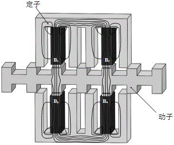
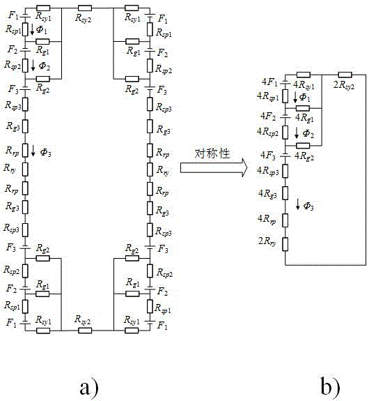
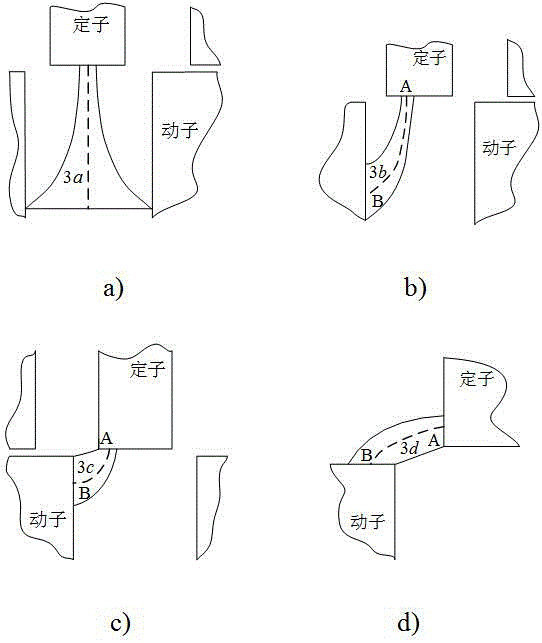
[0124] Such as figure 1 Shown is the structure of the bilateral switched reluctance linear motor and the schematic diagram of the magnetic field distribution of the typical mover position, the phase winding B of the switched reluctance linear motor 1 , B 2 , B 3 , B 4 Excitation, its magnetic circuit passes through the stator teeth, air gap, mover teeth, mover yoke, mover teeth, air gap, stator teeth, stator yoke, stator teeth, air gap, mover teeth, mover yoke, The mover teeth, air gap, stator teeth, and stator yoke are closed, and the equivalent magnetic circuit is as figure 2 Shown. According to the structural symmetry of the switched reluctance linear motor and the basic law of the magnetic circuit, the figure 2 a) The magnetic circuit shown is equivalent to figure 2 b) The magnetic circuit shown. The air gap reluctance is divided into three parts, n...


PUM


Abstract

The invention discloses a switched reluctance linear motor magnetic circuit modeling method especially suitable for switched reluctance linear motors of various phase number structures and belongs to the field of switched reluctance linear motor modeling and controlling. The switched reluctance linear motor magnetic circuit modeling method is characterized in that all calculation formulas of reluctance components in six magnetic circuits at a rotor position xu where the central line of a rotor groove is aligned at the central line of a stator tooth, at a rotor position x0 where the front edge of a rotor tooth is aligned at the front edge of the stator tooth, at a rotor position x1/4 where the rotor tooth and the stator tooth are overlapped by one four of width of the stator tooth, at a rotor position x1/2 where the rotor tooth and the stator tooth are overlapped by one half of the width of the stator tooth, at a rotor position x3/4 where the rotor tooth and the stator tooth are overlapped by three fourths of the width of the stator tooth and at a rotor position xa where the central line of the rotor tooth is aligned at the central line of the stator tooth are combined to form a magnetic circuit model of a switched reluctance linear motor. A motor electric magnetic field finite element method does not need to be adopted to calculate magnetic characteristics of the motor, the method is suitable for the switched reluctance linear motors of various phase number structures, quick design, realtime simulation and realtime control of a switched reluctance linear motor system can be realized, and the method has good engineering application value.

Description

Technical field [0001] The invention relates to a magnetic circuit modeling method of a switched reluctance linear motor, which is particularly suitable for switched reluctance linear motors with various phase number structures, and belongs to the field of modeling and control of switched reluctance linear motors. Background technique [0002] The switched reluctance linear motor has the advantages of simple structure, strong fault tolerance, high reliability, and simple control. It can also directly convert electrical energy into mechanical energy for linear motion without an intermediate mechanical conversion mechanism, which improves energy conversion efficiency. However, due to the double salient structure and magnetic saturation characteristics of the switched reluctance linear motor, the model is highly nonlinear and the mathematical analysis model is complicated. At present, the magnetic characteristics of switched reluctance linear motors are mainly calculated by using th...

Claims


Application Information

Patent Timeline
IPC IPC(8): G06F17/50
CPCG06F30/20
Inventor 陈昊闫文举刘征陈磊王星邓文慧孙萌
Owner CHINA UNIV OF MINING & TECH
Why Eureka
Try Eureka