Switching device applied to low voltage, medium voltage and high voltage short circuit arc extinction

A switch device, medium voltage technology, applied in the direction of electric switch, closed switch, explosion switch, etc., can solve the problems of loss, short-circuit device failure, etc., and achieve the effect of increasing the pressure of the cylinder, preventing rebound and improving reliability

Active Publication Date: 2016-08-17
710TH RES INST OF CHINA SHIPBUILDING IND CORP +1
View PDF9 Cites 7 Cited by
  • Summary
  • Abstract
  • Description
  • Claims
  • Application Information

AI Technical Summary

Problems solved by technology

[0010] Both the moving contact and the static contact of the above-mentioned patent adopt a conical complementary structure. Although the springback of the static contact can be prevented through its str

Method used


Image

  • Switching device applied to low voltage, medium voltage and high voltage short circuit arc extinction
  • Switching device applied to low voltage, medium voltage and high voltage short circuit arc extinction
  • Switching device applied to low voltage, medium voltage and high voltage short circuit arc extinction

Examples


Embodiment 1

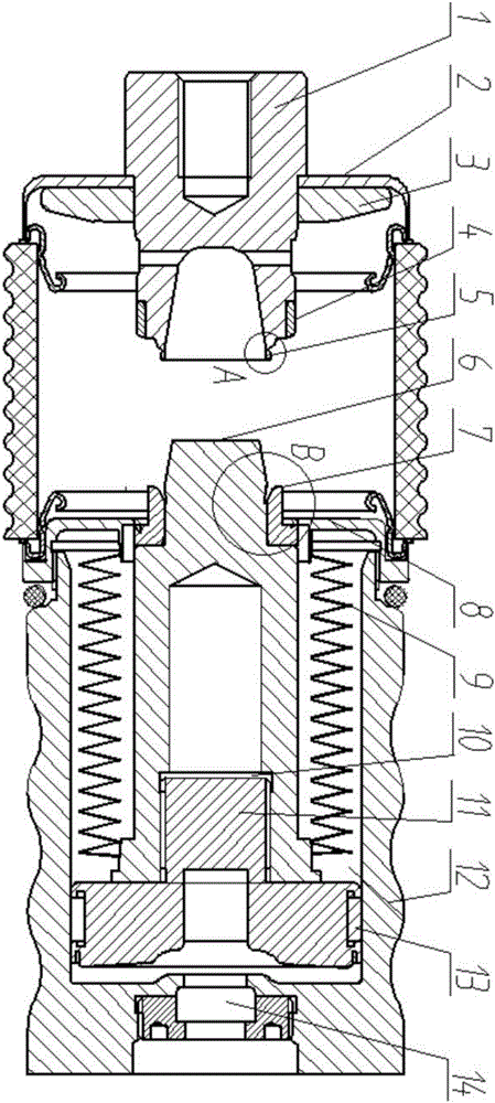
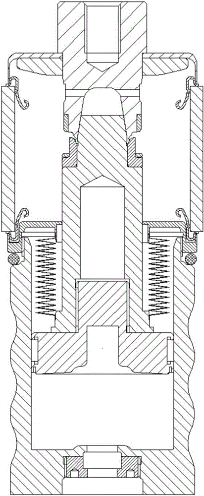
[0041] A switchgear for low-voltage, medium-voltage or high-voltage short-circuit arc extinguishing, including a housing 2, the two ends of the inner cavity of the housing 2 are respectively provided with a static contact 1, a cylinder 12, a piston 11 is provided in the cylinder 12, and the bottom of the cylinder 12 A gas generator 14 is provided, the front end of the piston 11 is provided with a movable contact 6, the piston 11, the cylinder 12 and the movable contact 4 are electrically connected, and the piston is also provided with a movable contact finger 13 to ensure that the piston 11 is in the process of moving. Fully electrically connected with the cylinder 12, an O-ring 10 is also provided between the piston and the moving contact, one end of the bellows 9 is airtightly connected with the energy storage acceleration shear plate 8 set on the inner wall of the housing, and the other end of the bellows 9 It is airtightly linked with the rear end of the moving contact 6, a...

Embodiment 2

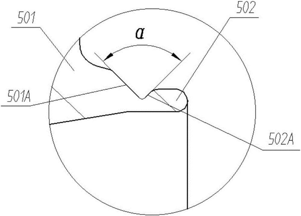
[0046] The difference from Example 1 is that the end of the static contact 1 is provided with a spherical opening, and the front end of the moving contact 6 is provided with a ball head complementary to the spherical opening, the angle β is preferably 5°, and the angle α is preferably is 60°.

[0047] Example 2

[0048] The difference from Embodiment 1 is that the end of the static contact 1 is provided with a cylindrical opening, the front end of the moving contact 6 is provided with a column head complementary to the cylindrical opening, the opening end of the static contact and the column head end of the moving contact All parts are chamfered, the cylindrical opening of the static contact is provided with conductive static contact fingers, the β angle is preferably 15°, and the α angle is preferably 120°.


PUM


Abstract

The invention relates to a switching device applied to low voltage, medium voltage and high voltage short circuit arc extinction. The device comprises a casing, wherein a fixed contact and an air cylinder are arranged at the two ends of a casing inner chamber respectively, a piston is arranged in the air cylinder, a gas generator is arranged at the bottom of the air cylinder, a moving contact is arranged at the front end of the piston, the air cylinder, the piston and the moving contact are electrically connected, a vacuum chamber is formed in one side, close to the fixed contact, of the casing inner chamber, an anti-rebounding buckle is arranged at the front end of the fixed contact, a guide limit groove corresponding to the anti-rebounding buckle is formed in the front end of the moving contact, the front end of the anti-rebounding buckle and the guide limit groove are at an included angle beta ranging from 5 degrees to 15 degrees, a limit ring is arranged on the moving contact, the guide limit groove is formed between the limit ring and the moving contact, and when the moving contact is hit into the fixed contact, the anti-rebounding buckle is inserted into the guide limit groove. The switching device applied to low voltage, medium voltage and high voltage short circuit arc extinction has the advantage that the locking reliability is higher.

Description

technical field [0001] The invention relates to a switchgear, in particular to a short-circuit switchgear used in short-circuit systems for low-voltage, medium-voltage and high-voltage short-circuit arc extinguishing. Background technique [0002] Low-voltage, medium-voltage and high-voltage switchgear components have the task of distributing energy flows and ensuring safe operation. In the unlikely event of an internal fault (fault arc), the safety of the installation and the safety of persons must also be ensured. Due to its temperature, an arc fault occurring within a switchgear assembly produces a sharp gas pressure rise within a period of a few milliseconds, and this can cause the switchgear assembly to be destroyed by an explosion. Therefore, take steps to dissipate the pressure as quickly as possible. Furthermore, it is desirable to confine arc faults to the relevant area and never endanger operators. [0003] By proper design, eg by internal subdivision (division ...

Claims


Application Information

Patent Timeline
IPC IPC(8): H01H39/00
CPCH01H39/004
Inventor 黄生华许三祥丁建龙蒋平陈江蔡昊席运桥赵洪艳田跃华余湖清
Owner 710TH RES INST OF CHINA SHIPBUILDING IND CORP
Why Eureka
Try Eureka