Method for rapidly estimating thickness of photosensitive element chip in infrared focal plane detector

A technology of infrared focal plane and photosensitive elements, which is applied in the direction of electrical components, semiconductor/solid-state device testing/measurement, circuits, etc., to achieve the effect of meeting the needs of mass production

Inactive Publication Date: 2016-08-17
昊瑞信通技术有限公司
View PDF3 Cites 1 Cited by
  • Summary
  • Abstract
  • Description
  • Claims
  • Application Information

AI Technical Summary

Problems solved by technology

[0004] The technical problem to be solved by the present invention is to provide a method for quickly estimating the thickness of the photosensitive element chip in the infrared focal plane detector, which can quickly estimate the photosensitive element chip of the infrared focal plane detector in the implementation of the back thinning process without loss Thickness, to solve the current problem of thickness estimation of photosensitive element chip

Method used


Image

  • Method for rapidly estimating thickness of photosensitive element chip in infrared focal plane detector
  • Method for rapidly estimating thickness of photosensitive element chip in infrared focal plane detector
  • Method for rapidly estimating thickness of photosensitive element chip in infrared focal plane detector

Examples


Embodiment Construction

[0023] The present invention will be described in further detail below in conjunction with the examples.

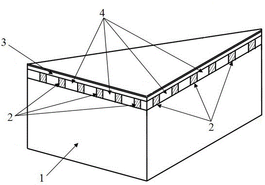
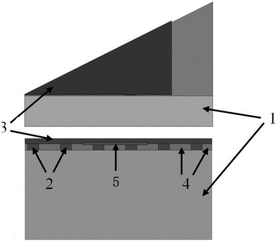
[0024] Deformation analysis of an indium antimonide (InSb) infrared focal plane detector with a scale of 128×128 arrays. The detector is composed of an InSb photosensitive element chip and a silicon readout circuit interconnected through an indium column array, and then an underfill glue is filled in the gap between the photosensitive element chip and the silicon readout circuit.

[0025] The simulation process is as follows:

[0026] 1) The viscoplastic model is used for the indium column, the viscoelastic Maxwell model is used for the bottom filling, and the linear elastic model is used for the photosensitive element chip, negative electrode and silicon readout circuit to conduct direct coupling field analysis;

[0027] 2) Input the Young's modulus, linear expansion coefficient, Poisson's ratio and density of the photosensitive element chip, the interconnected indium c...


PUM


Abstract

A method for rapidly estimating the thickness of a photosensitive element chip in an infrared focal plane detector includes the steps that 1, when the thickness of the photosensitive element chip is reduced to 20 microns, a concave annulus appears on the upper part of a negative electrode region; 2, when the thickness of the photosensitive element chip is reduced to 14 microns, besides the typical concave annulus, checkerboard buckling deformation patterns appear on the two sides of the negative electrode region; 3, when the thickness of the photosensitive element chip is reduced to 10 microns, besides the concave annulus and the checkerboard buckling deformation, up-convex deformation appears over indium bumps connected with negative electrodes at the concave annulus; 4, when the thickness of the photosensitive element chip is reduced to 6 microns, the valley-to-peak difference of the checkerboard buckling deformation is further increased. Compared with an existing method, the method for rapidly estimating the thickness has the advantages that non-contact, non-destruction, rapidness and accuracy are achieved, and the batch production requirement can be met.

Description

technical field [0001] The invention belongs to the field of estimating the thickness of a photosensitive element chip in the back thinning process of an infrared focal plane detector, in particular to a method for rapidly estimating the thickness of a photosensitive element chip in an infrared focal plane detector. Background technique [0002] The infrared focal plane detector is a detector that can convert the infrared radiation emitted by the detected object into a photoelectric signal, and then process the photoelectric signal to obtain the temperature distribution image of the measured object. Infrared focal plane detection technology has the advantages of wide spectral response band and can work day and night, so it is widely used in military and civilian fields such as missile early warning, intelligence reconnaissance, damage effect assessment, and agricultural and forest resource investigation. The typical structure of infrared focal plane detector is as follows: ...

Claims


Application Information

Patent Timeline
IPC IPC(8): H01L21/66
CPCH01L22/12
Inventor 张晓玲孟庆端张茉莉李艳霞高艳平张明川张立文普杰信
Owner 昊瑞信通技术有限公司
Why Eureka
Try Eureka