Eureka AIR delivers breakthrough ideas for toughest innovation challenges, trusted by R&D personnel around the world.

Improved Buck converter based on pulse sequence control

A pulse sequence and converter technology, applied in the field of improved Buck converters based on pulse sequence control, to achieve the effect of eliminating low-frequency fluctuations

Inactive Publication Date: 2016-08-17
CHINA UNIV OF MINING & TECH
View PDF5 Cites 0 Cited by
  • Summary
  • Abstract
  • Description
  • Claims
  • Application Information

AI Technical Summary

Problems solved by technology

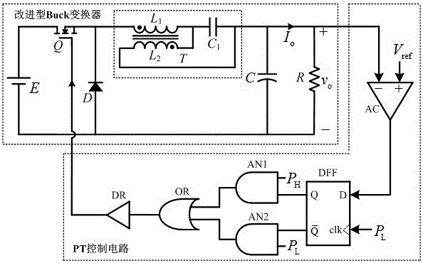
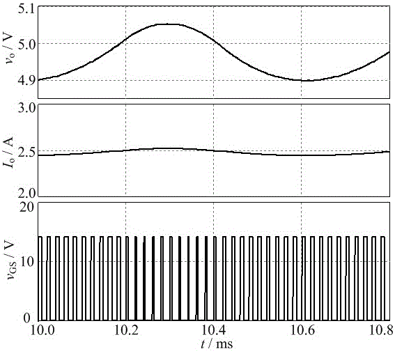
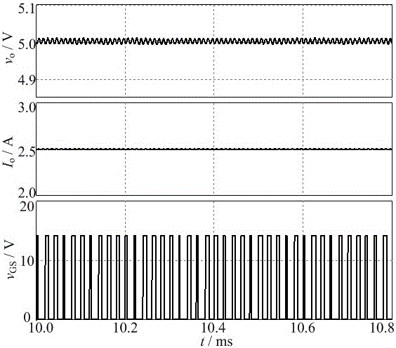
[0004] Aiming at the low-frequency fluctuation problem existing in the PT-controlled CCM Buck converter, the present invention proposes an improved Buck converter, which eliminates the low-frequency fluctuation phenomenon

Method used


Image

  • Improved Buck converter based on pulse sequence control
  • Improved Buck converter based on pulse sequence control
  • Improved Buck converter based on pulse sequence control

Examples


Embodiment Construction

[0012] The technical solution of the present invention will be described in detail below in conjunction with the accompanying drawings and embodiments.

[0013] figure 1 It is a block diagram of a PT control improved Buck converter circuit, which is composed of an improved Buck converter and a PT control circuit. The PT control circuit is composed of comparator AC, D flip-flop DFF, AND gate AN1, AN2, OR gate OR, and drive circuit DR; the improved Buck converter includes: power supply E, MOS tube Q, diode D, coupled inductor T, Non-polar capacitor C 1 , the output filter capacitor C and the load R; it is characterized in that the improved Buck converter is evolved from the Buck topology, and the energy storage inductance in the Buck converter is replaced by a pair of coupling inductors T; the MOS tube Q leaks The pole is connected to the positive pole of the input power supply E; the same-named terminal on the primary side of the coupling inductor T, the cathode of the diode ...


PUM


Abstract

The invention relates to an improved Buck converter based on pulse sequence control. The improved Buck converter comprises an improved Buck converter body and a PT control circuit, wherein the improved Buck converter body is evolved from Buck topology, and an energy storage inductor in the Buck converter body is replaced by a pair of coupled inductors. Dotted terminals of T primary sides of the coupled inductors, a cathode of a diode D and a Q source of an MOS (metal oxide semiconductor) transistor are connected; non-dotted terminals of primary sides, dotted terminals of secondary sides and one end of a non-polarized capacitor C1 are connected; non-dotted terminals of secondary sides, the other end of an intermediate capacitor C1, the anode of an output filter capacitor C and one end of a load R are connected. The low frequency fluctuation phenomenon of output voltage can be eliminated when the improved Buck converter operates in a continuous conductive mode.

Description

technical field [0001] The invention relates to an improved Buck converter, in particular to an improved Buck converter based on pulse sequence control. Background technique: [0002] Pulse train (PT) control is a novel non-linear discrete control technology for switching converters, it does not need compensation network, and the control circuit is simple to implement. The PT control switching converter has a fast dynamic response capability that cannot be compared with the traditional pulse width modulation (PWM) linear control switching converter, and is very suitable for switching power supply control systems with high reliability requirements. [0003] PT control is a control method proposed for the inductor current discontinuous conduction mode (DCM) switching converter, which essentially controls the input energy of the switching converter. In a switching cycle, the inductance energy storage of the switching converter is zero, and all the input energy is transferred t...

Claims


Application Information

Patent Timeline
Patent Type & Authority Applications(China)
IPC IPC(8): H02M3/157
CPCH02M3/157
Inventor 于东升王龙朱虹魏钰金
Owner CHINA UNIV OF MINING & TECH
Why Eureka
Eureka Blog
Learn More