
A kind of directional drive with composite foot support

A foot support and driver technology, which is applied in the direction of piezoelectric effect/electrostrictive or magnetostrictive motors, generators/motors, electrical components, etc., can solve the problem of increased distance between two foot supports and different sliding distances , the structure of the micro piezoelectric driver is complex, etc.

Active Publication Date: 2018-02-02
谐振机电精密技术(苏州)有限公司
View PDF3 Cites 0 Cited by
  • Summary
  • Abstract
  • Description
  • Claims
  • Application Information

AI Technical Summary

Problems solved by technology

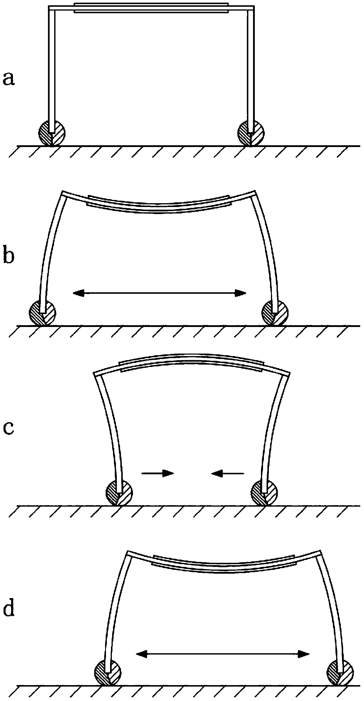
[0003] In order to solve the problems of complex structure and poor environmental adaptability of the current general micro-sized piezoelectric actuators, a directional actuator with a composite foot support is proposed, which consists of a piezoelectric vibrator, a first support leg, a second support leg, and a second support leg. One foot support and second foot support, the piezoelectric vibrator undergoes reciprocating bending deformation when energized, so that the distance between the two foot supports increases or decreases. During the reciprocating movement of the foot support, due to the existence of friction The material with friction coefficient is alternately in contact with the working surface, so the sliding distance of the foot support is different when it moves forward and reverse, forming the driving ability in the direction of the material with low friction coefficient

Method used


Image

  • A kind of directional drive with composite foot support
  • A kind of directional drive with composite foot support
  • A kind of directional drive with composite foot support

Examples


Embodiment Construction

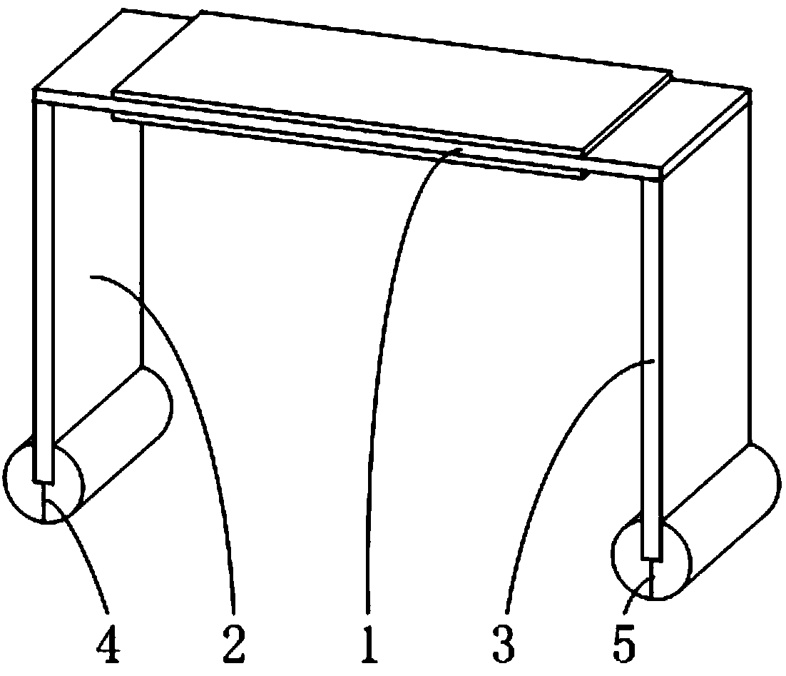
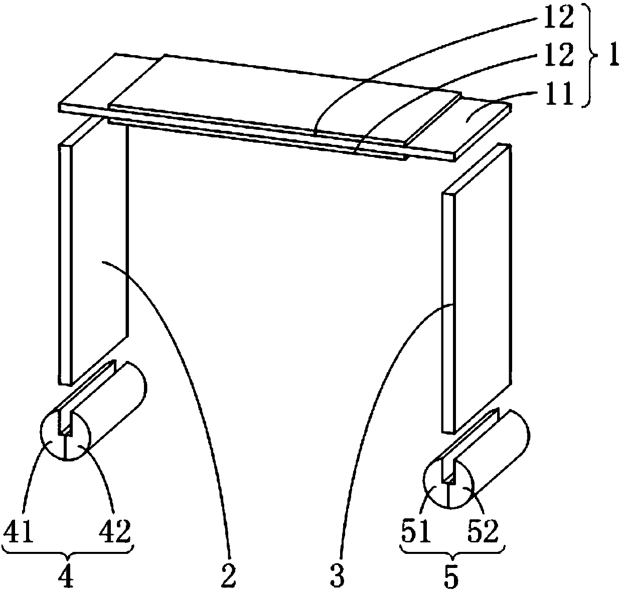
[0010] refer to figure 1 , figure 2 and image 3 , a directional driver with a composite foot support in the present invention is composed of a piezoelectric vibrator 1, a first support leg 2, a second support leg 3, a first foot support 4 and a second foot support 5, wherein:

[0011] The piezoelectric vibrator 1 is composed of an elastic substrate 11 and a piezoelectric thin sheet material 12 attached to its upper and lower surfaces; the first support leg 2 and the second support leg 3 are rectangular thin plate structures with the same size and shape; The first support leg 2 and the second support leg 3 have a certain degree of elasticity, and can realize bending deformation at a small angle; the end surface of one end of the first support leg 2 is pasted on the lower surface of the first end of the piezoelectric vibrator 1, and the other end is a free end; the end surface of one end of the second support leg 3 is pasted on the lower surface of the second end of the piez...


PUM


Abstract

The invention relates to a directional driver with a composite foot support seat. The directional driver comprises a piezoelectric vibrator, a first support leg, a second support leg, a first foot support seat and a second foot support seat, wherein the piezoelectric vibrator consists of an elastic base plate and piezoelectric thin sheet materials attached to the upper and lower surfaces of the elastic base plate; the first support leg and the second support leg are of rectangular thin plate structures with certain elasticity, can realize the small-angle bending and deformation, and are respectively arranged at the two ends of the piezoelectric vibrator; the first foot support seat and the second foot support seat are formed by compounding two kinds of materials with different friction coefficients, and are respectively arranged on the first support leg and the second support leg. The device is used as the driver, is mainly used in the fields of soft robots, decoration and rescue, biological medical care and the like, and has the advantages that the structure is simple, the environment adaptability is high, and the like.

Description

technical field [0001] The invention belongs to the field of piezoelectric driving, and in particular relates to a directional driver with a composite foot support. Background technique [0002] With the development of science and technology, micro-drive technology occupies an increasingly important position in the fields of ultra-precision machinery and its manufacturing, precision measurement, detection and rescue, and biomedicine. New types of drives have been developed one after another. With the development of piezoelectric drive technology, the drive with piezoelectric ceramics as the core functional material stands out in the field of ultra-precision positioning drives. Piezoelectric ceramic drivers have the advantages of high energy density, fast response, high resolution, anti-electromagnetic interference, and low-temperature vacuum environment resistance. However, the existing piezoelectric micro-drivers have complex structures, difficult processing, and are not ...

Claims


Application Information

Patent Timeline
IPC IPC(8): H02N2/02H02N2/04
CPCH02N2/021H02N2/04
Inventor 吴越曾祥莉刘庆萍任露泉王京春涂前进宋正义
Owner 谐振机电精密技术(苏州)有限公司
Learn More