Image coding method and device, and image decoding method and device
A technology of image coding and coding blocks, which is applied in image coding, image communication, image data processing, etc., can solve the problems of low efficiency, achieve the effect of overcoming low efficiency, improving coding compression efficiency and decoding and decompression efficiency
- Summary
- Abstract
- Description
- Claims
- Application Information
AI Technical Summary
Problems solved by technology
Method used
Image
Examples
Embodiment 1
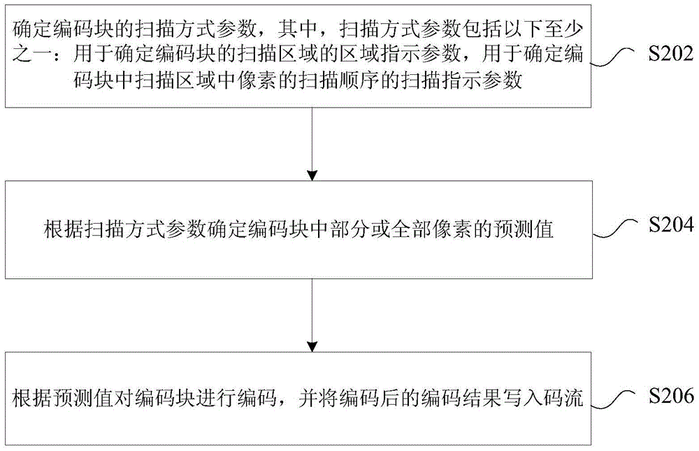
[0068] In this embodiment, an image coding method is provided, figure 2 is a flow chart of an optional image coding method according to an embodiment of the present invention, such as figure 2 As shown, the process includes the following steps:
[0069] S202. Determine the scanning mode parameters of the encoding block, where the scanning mode parameters include at least one of the following: an area indication parameter for determining the scanning area of the encoding block, and a scanning indication for determining the scanning order of pixels in the scanning area of the encoding block parameter;
[0070] S204. Determine the predicted values of some or all pixels in the coding block according to the scanning mode parameters;
[0071] S206. Encode the encoding block according to the predicted value, and write the encoded encoding result into the code stream.
[0072] Optionally, in this embodiment, the above-mentioned image coding method can be applied to the vide...
Embodiment 2
[0157] In this embodiment, an image decoding method is provided, Figure 10 is a flowchart of an optional image decoding method according to an embodiment of the present invention, such as Figure 10 As shown, the process includes the following steps:
[0158] S1002, analyzing the code stream to obtain decoding parameters of the decoding block;
[0159] S1004. Obtain scan mode parameters according to the decoding parameters, where the scan mode parameters include: an area indication parameter used to determine the scan area of the decoded block, and / or a scan indication parameter used to determine the scan order of pixels in the scan area;
[0160] S1006. Determine reconstruction values of some or all pixels in the decoded block according to the area indication parameter and / or the scan indication parameter.
[0161] Optionally, in this embodiment, the above-mentioned image decoding method can be applied to the video image decoding process, but not limited to, for exampl...
Embodiment 3
[0242] In this embodiment, an image encoding device is also provided, which is used to implement the above embodiments and preferred implementation modes, and what has been described will not be repeated here. As used below, the term "module" may be a combination of software and / or hardware that realizes a predetermined function. Although the devices described in the following embodiments are preferably implemented in software, implementations in hardware, or a combination of software and hardware are also possible and contemplated.
[0243] In this embodiment, an image encoding device is provided, Figure 11 is a schematic diagram of an optional image encoding device according to an embodiment of the present invention, such as Figure 11 shown, including:
[0244] 1) The first determining unit 1102 is configured to determine the scanning mode parameters of the coding block, wherein the scanning mode parameters include at least one of the following: an area indication parame...
PUM
 Abstract
Description
Claims
Application Information
 - R&D
- Intellectual Property
- Life Sciences
- Materials
- Tech Scout
- Unparalleled Data Quality
- Higher Quality Content
- 60% Fewer Hallucinations
Browse by: Latest US Patents, China's latest patents, Technical Efficacy Thesaurus, Application Domain, Technology Topic, Popular Technical Reports.
© 2025 PatSnap. All rights reserved.Legal|Privacy policy|Modern Slavery Act Transparency Statement|Sitemap|About US| Contact US: help@patsnap.com


