
Combined cleaning device for waste gas of low speed marine diesel engine

A technology for washing devices and diesel engines, which is used in combination devices, exhaust devices, mufflers, etc., can solve the problems of insignificant removal of fine particles, unsatisfactory removal of particles, and increased resistance. The effect of increasing the gas-liquid contact area and reducing energy consumption

Active Publication Date: 2016-08-24
HARBIN ENG UNIV
View PDF9 Cites 6 Cited by
  • Summary
  • Abstract
  • Description
  • Claims
  • Application Information

AI Technical Summary

Problems solved by technology

[0006] Patent "A joint removal device for exhaust gas pollutants for two-stroke diesel engines (201410374452.6)", this patent uses spray technology to remove SO2 and particulate matter, and the tower shape is a packed tower. This technology is more widely used in propagation Extensive wet scrubbing technology, high removal efficiency for SO2, but unsatisfactory removal effect for particulate matter
[0007] Patent "A ship tail gas-tower desulfurization and particle removal device and its use method (201310344800.0)", this patent uses multi-layer packing and spraying to remove SO2 and particulate matter, which can remove SO2 and larger particles, but due to its multi-layer filler, the resistance is increased, and the removal effect on fine particles is not obvious, and the energy consumption is high

Method used


Image

  • Combined cleaning device for waste gas of low speed marine diesel engine

Examples


Embodiment Construction

[0015] Hereinafter, the present invention will be described in more detail with examples in conjunction with the accompanying drawings:

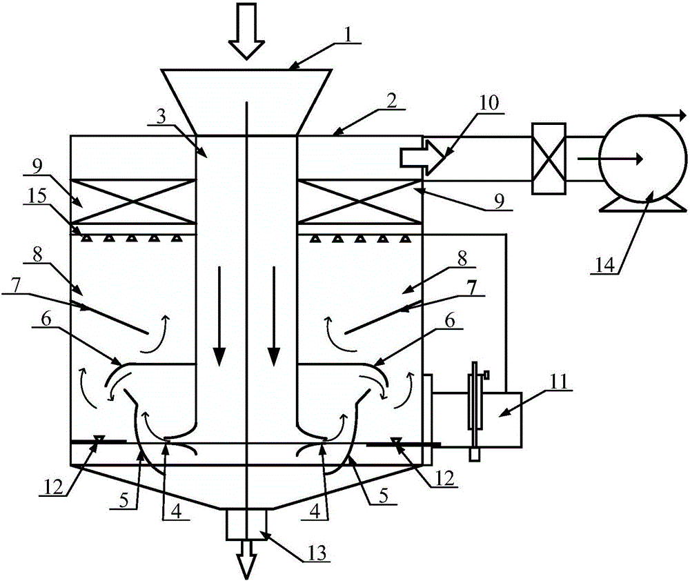
[0016] Combine figure 1 , The composite scrubbing device for low-speed diesel engine exhaust gas of a ship of the present invention mainly includes a scrubber 2 and a water supply system 11. The scrubber 2 includes an air inlet 1, an air inlet 3, a gas nozzle 4, a baffle 5-7, a washing zone 8, a liquid film nozzle 12, a spray layer 15, a mist eliminator 9, an exhaust port 10 and a drain 口13. In addition, the device also includes an induced draft fan 14. It is characterized in that: the air inlet 1 is connected with the air inlet 3, the air inlet 3 is connected to the washing zone 8 through the gas nozzle 4, and the liquid film nozzle 12, the baffle 5-7, and the spray nozzle are arranged in the washing zone from bottom to top. The shower layer 15 and the demister 9, the induced draft fan 14 are connected to the scrubber 2 through the exhaust p...


PUM


Abstract

The invention aims to provide a combined cleaning device for waste gas of a low speed marine diesel engine. The combined cleaning device comprises a cleaning device and a water supply system. The cleaning device comprises a shell and an air inlet duct wall arranged in the shell, an air inlet duct is formed in the air inlet duct wall, a cleaning region is formed between the air inlet duct wall and the shell, a demister and a spray layer are arranged in the cleaning region from top to bottom, a drainage opening is formed in the lower end of the shell, liquid membrane nozzles are arranged above the drainage opening and fixed to the inner wall of the shell, air nozzles are arranged between the liquid membrane nozzles and the air inlet duct wall, a first baffle is arranged on each gas nozzle, a second baffle is arranged above each first baffle, a third baffle is arranged above each second baffle, and an exhaust opening is formed in the portion, above the demister, of the shell. The water supply system is connected with the spray layer and the liquid membrane nozzles. An atomization spray device is omitted, strong vortexes are formed by the baffles many times, the liquid atomization and air-liquid contact area is increased, reaction time is prolonged, and the collection efficiency of SO2 and particles is improved.

Description

Technical field [0001] The invention relates to an exhaust gas washing device, specifically a ship exhaust gas washing device. Background technique [0002] With the development of the shipping industry, the low-speed diesel engine of ships will further increase the content of SO2 and particulate matter due to its low-quality heavy oil. Countries and regions such as IMO, Europe, the United States, and China have also formulated strict regulations to limit emissions from ships, so the requirements for the control of exhaust emissions are becoming more and more stringent. The SO2 and particulate matter discharged into the air by the main and auxiliary engines of ships and oil-fired boilers and other fuel-burning devices will cause great harm to humans and the environment. The Chinese government has also formulated relevant regulations for the emission of ship exhaust pollutants and determined The core port area within the emission control area. [0003] At present, the technologies...

Claims


Application Information

Patent Timeline
IPC IPC(8): B01D50/00B01D53/92B01D53/78B01D53/50F01N3/04F01N3/08
CPCB01D53/50B01D53/78B01D53/92F01N3/04F01N3/08B01D2258/012F01N2590/02F01N2570/04B01D2251/80B01D2251/60B01D50/40
Inventor 朱元清周金喜周松王占广高瑞锋
Owner HARBIN ENG UNIV
Learn More