Automatically feeding type cutting machine for steel pipes

An automatic feeding and cutting machine technology, applied in the direction of grinding feed movement, grinding machine parts, grinding machines, etc., can solve the problems of unstable clamping of steel pipes, low efficiency, and burrs in the incision

Active Publication Date: 2016-08-24
ZHEJIANG ZHONGDA SPECIAL STEEL
View PDF7 Cites 9 Cited by
  • Summary
  • Abstract
  • Description
  • Claims
  • Application Information

AI Technical Summary

Problems solved by technology

[0003] The purpose of the present invention is to overcome the deficiencies of the above-mentioned prior art, and provide an automatic feeding steel pipe cutting machine, which aims to solve the difficulty in feeding and feeding materials in the prior art, low efficiency, unstable clamping of steel pipes, and burrs on the cut. and other technical issues

Method used


Image

  • Automatically feeding type cutting machine for steel pipes
  • Automatically feeding type cutting machine for steel pipes
  • Automatically feeding type cutting machine for steel pipes

Examples


Embodiment Construction

[0016] In order to make the object, technical solution and advantages of the present invention clearer, the present invention will be further described in detail below with reference to the accompanying drawings and embodiments. However, it should be understood that the specific embodiments described here are only used to explain the present invention, and are not intended to limit the scope of the present invention. Also, in the following description, descriptions of well-known structures and techniques are omitted to avoid unnecessarily obscuring the concept of the present invention.

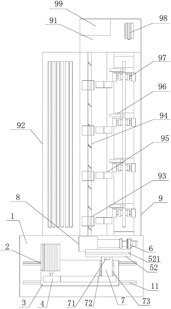
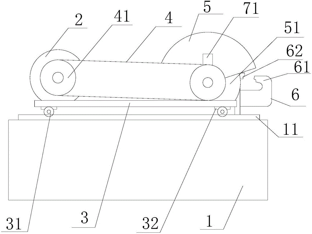
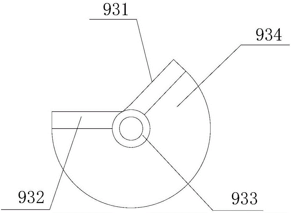
[0017] refer to figure 1 , figure 2 ,with image 3 , the embodiment of the present invention provides an automatic feeding steel pipe cutting machine, including a chassis 1, a motor 2, a slide 3, a power box 4, a cutting device 5, a clamping device 6, a transmission device 7, a hydraulic cylinder 8 and a feeding device 9. The chassis 1 is provided with several slide rails 11, the slide rai...


PUM


Abstract

The invention provides an automatically feeding type cutting machine for steel pipes. The automatically feeding type cutting machine for the steel pipes comprises a machine box, a motor, a sliding seat, a power box, a cutting device, a clamping device, a transmission device, a hydraulic cylinder and a feeding device, wherein a plurality of sliding rails are arranged on the machine box, the sliding seat is arranged on the sliding rails, a plurality of rollers are arranged on the sliding seat, the power box is arranged on the sliding seat, the motor is arranged on the machine box, the output shaft of the motor is connected with the input end of the power box, the transmission device is arranged at the rear of the power box, the output end of the power box is connected with the input end of the transmission device, the cutting device is mounted at the rear side of the transmission device, the output end of the transmission device is connected with the cutting device, the clamping device is arranged at the rear of the cutting device, and connected with the hydraulic cylinder, and the feeding device is arranged at the rear of the clamping device, therefore, the technical problems of difficult feeding, low efficiency and incision burrs caused by unstable steel pipe clamping and the like are solved.

Description

【Technical field】 [0001] The invention relates to the field of steel pipe feeding, in particular to an automatic feeding steel pipe cutting machine. 【Background technique】 [0002] Steel pipes are widely used in today's society, such as petrochemical industry and heat exchangers, etc., but the specifications of steel pipes on the market are fixed, sometimes it is difficult to buy the size you want, and Or sometimes the requirements for the steel pipe are not very high, and because the steel pipe itself has a large net weight and a long length, the general method is to fix the steel pipe first, and then use a cutting machine to cut the required length. More, the steel pipe is very troublesome to operate when feeding and cutting, which increases the labor intensity of the operator, and the work efficiency is also low. The inclination of the feeding rack and the slow fall of the steel pipe's own weight often cause an accidental Multiple steel pipes are loaded, causing multiple...

Claims


Application Information

Patent Timeline
Patent Type & Authority Applications(China)
IPC IPC(8): B24B41/00B24B41/06B24B55/04B24B27/06
CPCB24B27/06B24B41/005B24B41/06B24B55/04
Inventor 金惠明李跃生高小华徐跃松顾计松
Owner ZHEJIANG ZHONGDA SPECIAL STEEL
Why Eureka
Try Eureka