Far knuckle unit of data glove

A technology of data gloves and fingers, applied in the directions of manipulators, manufacturing tools, joints, etc., can solve the problems of complex system, difficult maintenance, and high price.

Inactive Publication Date: 2016-08-24
苏茂
View PDF0 Cites 0 Cited by
  • Summary
  • Abstract
  • Description
  • Claims
  • Application Information

AI Technical Summary

Problems solved by technology

[0003] The purpose of the present invention is to solve the disadvantages of the existing force feedback data gloves, such as high price, complex system, and difficult maintenance, and proposes a combination of an external potentiometer and a joint bidirectional active drive

Method used


Image

  • Far knuckle unit of data glove
  • Far knuckle unit of data glove
  • Far knuckle unit of data glove

Examples


specific Embodiment approach 1

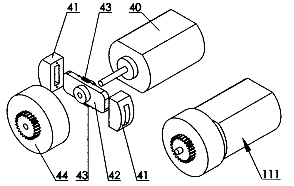
[0007] Specific implementation mode one: as image 3 As shown, the data glove far knuckle unit includes a driving part 111, and the driving part 111 includes a micro motor 40 and a clutch device, and the clutch device is composed of a clutch device friction plate 41, a friction plate slide bar 42, a return pull The spring 43 and the clutch device cover 44 are composed of the friction plate slide bar 42 and the shaft of the micro-motor 40. Be connected with return extension spring 43, clutch device cover 44 is inserted into the shaft of micromotor 40, be sliding contact between the shaft of clutch device cover 44 and micromotor 40, and clutch device cover 44 is provided with transmission gear. Action implementation process: when the rotation speed of the micro motor 40 is higher than a certain value, the two friction plates 41 of the clutch device overcome the tension of the return tension spring 43 and slide to the two ends of the friction plate slide bar 42 respectively and c...

specific Embodiment approach 2

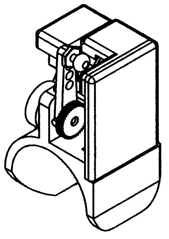
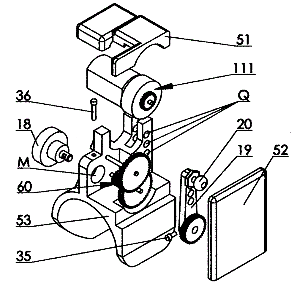
[0008] Specific implementation mode two: as figure 1 , figure 2 and image 3 As shown, the data glove distal knuckle unit includes a driving part 111 , a potentiometer 18 , a rocker arm 19 , a gear case cover 57 and a knuckle base 58 . The knuckle base 58 is provided with a hole seat P and a row of mounting holes R for the ball head 20 or the screw 24, and the potentiometer 18 is fixed in the hole seat P of the knuckle base 58 by a screw 36, The shaft of the potentiometer 18 in the hole seat P is fixedly connected to the rocking arm 19 by a screw 35, the gear axis on the rocking arm 19 coincides with the axis of the rocking arm rotation, and the gear of the rocking arm 19 is reduced by deceleration. The gear set 60 is engaged with the gears of the driving part 111, the driving part 111 is installed on the knuckle base 58, the other end of the rocker arm 19 is fixed to the ball head 20, and the ball head 20 is connected to the corresponding measured Component connections. ...


PUM


Abstract

The invention discloses a far knuckle unit of a data glove, and relates to a device detecting motion states of human hand fingers and feeding back forces applied on corresponding finger joints of a slave hand. In order to overcome the shortcomings that an existing knuckle detection mechanism of a force feedback device is separated from a force feedback mechanism, system is complicated, structure is bulky, maintenance is difficult, bi-directional active driving cannot be achieved and cost is high, the knuckle detection mechanism is integrated with the force feedback mechanism, a unique connection method and a smart knuckle detecting point layout are adopted, the maximum flexibility of fingers to be detected can be maintained when an operator uses the far knuckle unit of the data glove, and the motion states can be accurately detected, so that the corresponding finger joints of the slave hand under control move consistently with the corresponding finger joints of the operator, and force bearing situation of the slave hand in a specific work environment can be fed back to the operator to enhance the sense of immediacy of virtual reality or teleoperation.

Description

technical field [0001] The invention relates to a device which detects the movement state of human fingers and has the function of two-way feedback force. Background technique [0002] Due to the development of science and technology, robots are gradually being used in an increasing range. As a reliable and mature robot, teleoperation robots are widely used in various dangerous, complex and inaccessible environments. It uses a very reliable control method, which is directly controlled by the operator's instructions. As the tasks performed by teleoperated robots become more and more complex, people put forward higher requirements for their flexibility while pursuing reliability, and it is necessary to implement teleoperation on complex manipulators to control the movement of multiple fingers of the manipulator. Multiple joints move together to achieve specific functions, which requires the use of data gloves, and the data glove with force feedback function is the most effect...

Claims


Application Information

Patent Timeline
IPC IPC(8): B25J17/00B25J3/00
Inventor 苏茂
Owner 苏茂
Why Eureka
Try Eureka