
A thin-film slicing and cutting device for splicing thin-film reflective surface antennas

A technology of cutting device and reflective surface, applied in metal processing and other directions, can solve the problems of cutting error, large difference between thin films, reducing the accuracy of reflective surface shape, etc., and achieve the effect of avoiding splicing errors, avoiding wrinkles, and simple operation.

Inactive Publication Date: 2017-11-28
XIDIAN UNIV
View PDF5 Cites 0 Cited by
  • Summary
  • Abstract
  • Description
  • Claims
  • Application Information

AI Technical Summary

Problems solved by technology

[0003] It should be noted that when cutting by hand, the uneven cutting force will lead to different degrees of wrinkles in the film, and this kind of wrinkles is difficult to eliminate through external force during the forming process of the reflective surface. The existence of wrinkles will significantly reduce the reflective surface. Surface accuracy
At the same time, it is easy to produce cutting errors during manual cutting, and the shape of the cut film sheet is quite different from the design value.

Method used


Image

  • A thin-film slicing and cutting device for splicing thin-film reflective surface antennas
  • A thin-film slicing and cutting device for splicing thin-film reflective surface antennas
  • A thin-film slicing and cutting device for splicing thin-film reflective surface antennas

Examples


Embodiment Construction

[0041] In order to make the object, technical solution and advantages of the present invention clearer, the present invention will be described in further detail in conjunction with the accompanying drawings and embodiments. It should be understood that the specific embodiments described here are only used to explain the present invention and are not intended to limit it. this invention.

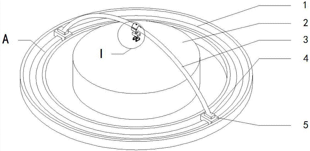
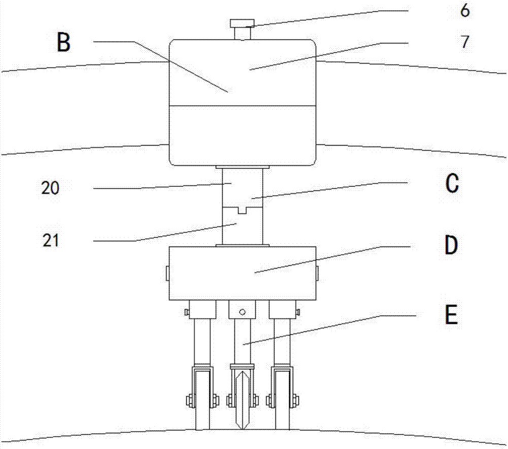
[0042] Such as Figure 1 to Figure 14 As shown, a film slice cutting device for splicing film reflector antennas is composed of a circular motion mechanism A, an arc-shaped motion mechanism B, a steering mechanism C, an adjustment mechanism D, a cutting mechanism E, and a film mold 2.

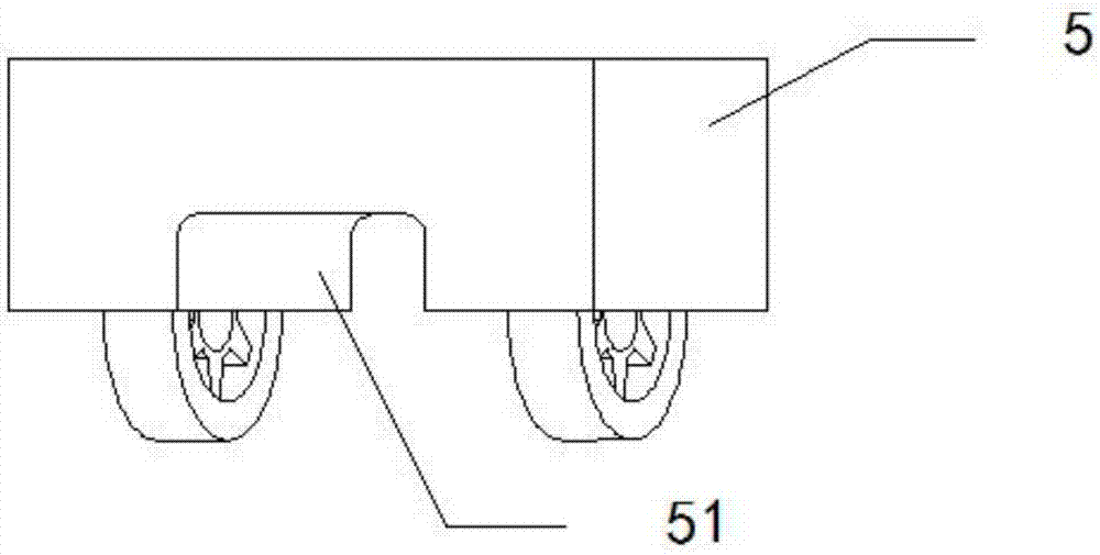
[0043] The circular motion mechanism A (see figure 1 ), consisting of a circular track 1, an arc-shaped guide rail placement table 4 and a sliding trolley 5 (see image 3 )composition. There is a boss in the middle of the circular track 1, and the number of sliding cars 5 is 2, which are symmetrically plac...


PUM


Abstract

The invention discloses a film slicing and cutting device for a spliced film reflector antenna. The film slicing and cutting device comprises an annular movement mechanism, an arc-shaped movement mechanism, a steering mechanism, a regulation mechanism, a cutting mechanism and a film mold, wherein the annular movement mechanism is composed of a circular track, skidding trolleys and arc-shaped guide rail placing tables; the arc-shaped movement mechanism is composed of an arc-shaped guide rail and a skidding sleeve; the steering mechanism is composed of an upper steering block and a lower steering block; the regulation mechanism is composed of a square cavity, regulation blocks, sleeves and pressure shafts; the cutting mechanism is composed of a cutting device and compacting devices; the cutting device is composed of a hob and a connecting board; each compacting device is composed of an annular flat band, flat band wheels and a linking board; the film mold is arranged at the middle part of the annular movement mechanism and with the same axis with the circular track; and the upper surface of the film mold is in a shape of a paraboloid of revolution. The film slicing and cutting device can circumferentially and radially cut a film reflector in a blocking manner, is simple in cutting operation, good in cutting effect and high in cutting accuracy and can effectively prevent cutting folds from ocurring.

Description

technical field [0001] The invention relates to the technical field of film cutting, in particular to a film slice cutting device for splicing film reflector antennas with simple operation, high cutting precision and effective avoidance of wrinkles. Background technique [0002] The thin film reflective surface is a new type of reflective surface that has appeared in recent years. It achieves the purpose of reflecting electromagnetic waves by coating a layer of metal reflective medium on the polyimide film material. It has low surface density, small folded volume, portable and expandable, The advantages of easy control and low cost. The production of thin film reflective surface is a key technology in the development of this type of antenna. The commonly used production methods include curved surface casting method and piece splicing method. Among them, the piece splicing method is suitable for large-diameter antennas and can obtain higher reflective surface accuracy. . ...

Claims


Application Information

Patent Timeline
Patent Type & Authority Patents(China)
IPC IPC(8): B26D1/18B26D7/26
CPCB26D1/185B26D7/2621B26D7/2635B26D2007/2657
Inventor 张腾杜敬利赵泽张逸群李申蒋翔俊
Owner XIDIAN UNIV
Learn More