Electric wire and cable winding and unwinding device

A retractable device, wire and cable technology, applied in the directions of transportation and packaging, transportation of filamentous materials, thin material processing, etc., can solve the problems of inability to retract cables in zones, inability to complete storage and winding, and low retraction efficiency, etc. Good winding and storage of cables, increasing winding efficiency and convenient movement

Active Publication Date: 2016-08-24
JURONG FUDA ELECTRIC TECH
View PDF7 Cites 22 Cited by
  • Summary
  • Abstract
  • Description
  • Claims
  • Application Information

AI Technical Summary

Problems solved by technology

[0002] After the cable is produced, it is necessary to wind a whole cable into a bundle and place it, usually through a cable retracting device, while the existing wire and cable retracting device has a simple structure and a single function; it has many disadvantages; The first is that the length of the winding shaft is fixed, so the length of the cable it accommodates is also fixed. If the cable wire is long, the storage and winding cannot be completed; the second is that the shaft of most cable retracting devices is a shaft. The length of the wound cable is fixed, and the efficiency of retracting and unwinding is not high, resulting in a waste of energy; third, most of the shafts can only be wound with one cable, and the cables cannot be retracted and unwrapped in different areas; download is more troublesome

Method used


Image

  • Electric wire and cable winding and unwinding device
  • Electric wire and cable winding and unwinding device
  • Electric wire and cable winding and unwinding device

Examples


Embodiment Construction

[0023] The present invention will be further illustrated below in conjunction with the accompanying drawings and specific embodiments. This embodiment is implemented on the premise of the technical solution of the present invention. It should be understood that these embodiments are only used to illustrate the present invention and are not intended to limit the scope of the present invention.

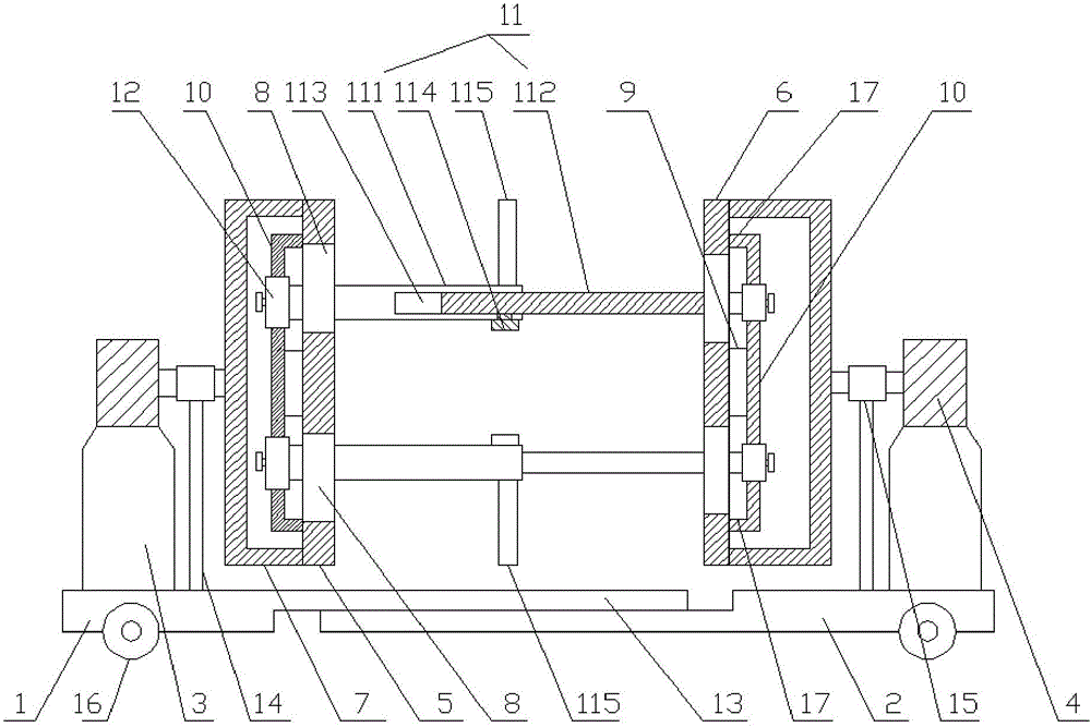
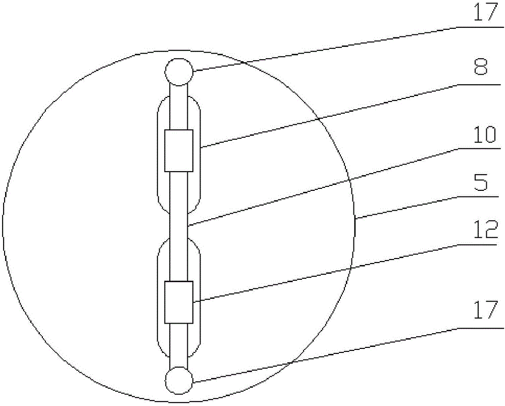
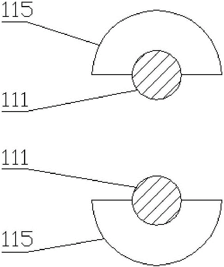
[0024] Such as figure 1 , figure 2 and image 3 As shown, a wire and cable retracting device includes a left base plate 1 and a right base plate 2; the left base plate 1 and the right base plate 2 are provided with mounting bases 3; the mounting bases 3 are equipped with servo motors 4 ; And the heights of the two servo motors 4 are the same, the directions are opposite, and the screw rods are arranged horizontally.

[0025] It also includes a cable retractable frame used in conjunction with the left and right side servo motors 4; the cable retractable frame includes a left side plat...


PUM


Abstract

The invention discloses an electric wire and cable winding and unwinding device which comprises a left bottom plate and a right bottom plate, wherein mounting bases are arranged on both of the left bottom plate and the right bottom plate; servo motors are mounted on both of the mounting bases; further, two servo motors are the same in heights but opposite in directions; screw rods are transversely arranged; the electric wire and cable winding and unwinding device also comprises a cable winding and unwinding rack used and matched with side servo motors on a left and a right; the cable winding and unwinding rack comprises a left side plate, a right side plate, and frames which are mounted on an outer side of the left side plate and an outer side of the right side plate. In the electric wire and cable winding and unwinding device, two spools are adopted to hold and wind an electric wire and a cable; the cable is wound on the spools, so that the cable can be held and wound; a certain space exists between the two spools; moreover, two ends of each of the two spools are mounted on loop bars through sleeves; the space between the two spools can be regulated through regulating the positions of the sleeves; after the space is increased, the length of the cable wound on the spools can be increased after the spools are rotated for one revolution each time; the winding efficiency of the cable is improved.

Description

technical field [0001] The invention relates to a cable production tool, in particular to a wire and cable retracting device. Background technique [0002] After the cable is produced, it is necessary to wind a whole cable into a bundle and place it, usually through a cable retracting device, while the existing wire and cable retracting device has a simple structure and a single function; it has many disadvantages; The first is that the length of the winding shaft is fixed, so the length of the cable it accommodates is also fixed. If the cable wire is long, the storage and winding cannot be completed; the second is that the shaft of most cable retracting devices is a shaft. The length of the wrapped cable is fixed, and the efficiency of retracting and unwinding is not high, resulting in a waste of energy; third, most of the shafts can only be wound with one cable, and the cables cannot be retracted and unwrapped in different areas; It is more troublesome to download. Cont...

Claims


Application Information

Patent Timeline
Patent Type & Authority Applications(China)
IPC IPC(8): B65H54/54B65H54/72B65H75/24
CPCB65H54/54B65H54/72B65H75/241B65H2701/34
Inventor 张鼎
Owner JURONG FUDA ELECTRIC TECH
Why Eureka
Try Eureka