Spiral type anaerobic fermentation system for making clean energy from plant straw

A technology of clean energy and plant straw, applied in bioreactor/fermenter combination, fermentation, bioreactor/fermenter for specific purposes, etc. system scrapping and other problems, to achieve the effect of promoting the uniform distribution of bacteria, improving the self-convection of biogas slurry, and increasing the maximum capacity

Inactive Publication Date: 2016-08-24
李俊
View PDF0 Cites 0 Cited by
  • Summary
  • Abstract
  • Description
  • Claims
  • Application Information

AI Technical Summary

Problems solved by technology

[0002] The air ducts of the existing biogas fermentation systems are mostly poured with concrete and fixed on the top of the gas storage plate, and the airtightness of the surrounding is not high, and the surrounding air leakage is difficult to block; since the fermentation raw materials of the biogas digester are mostly livestock manure, manure During the decay process, various insects are easy to breed. Maggots crawl into the airway tube and cause blockage, which is difficult to clean; when there is water in the airway tube, it is difficult to discharge; the most prominent problem is that when the airway tube breaks, it is difficult to replace and can Lead to the scrapping of the entire biogas fermentation system
[0003] The biogas storage space of the current hydraulic biogas fermentation system refers to the area between the gas baffles of the feed pipe and the gas baffles of the discharge pipe arranged at both ends of the fermentation chamber. When the stored biogas is not used for a long time, The stored biogas overflows from the bottom of the feed pipe air baffle, discharge pipe air baffle, and enters the air, causing waste; the existing biogas storage space is limited
[0004] The most important factors affecting biogas fermentation efficiency and gas production are fermentation raw materials, strains, and temperature. When the fermentation raw materials and strains are evenly distributed, microorganisms can fully decompose the fermentation raw materials, produce more biogas and make the temperature in the biogas storage chamber increase to further promote fermentation; in the existing biogas fermentation system, due to the poor fluidity of the biogas slurry, a large amount of fermentation raw materials are accumulated at the inlet. After long-term fermentation, the biogas slurry containing a large number of bacteria mainly accumulates at the outlet. As a result, the distribution of fermentation raw materials and strains in the fermentation system is uneven, which inhibits the fermentation efficiency and reduces the gas production.

Method used


Image

  • Spiral type anaerobic fermentation system for making clean energy from plant straw
  • Spiral type anaerobic fermentation system for making clean energy from plant straw
  • Spiral type anaerobic fermentation system for making clean energy from plant straw

Examples


Embodiment Construction

[0042] The technical solutions in the embodiments of the present invention will be clearly and completely described below in conjunction with the accompanying drawings in the embodiments of the present invention. Obviously, the described embodiments are only some, not all, embodiments of the present invention. Based on the embodiments of the present invention, all other embodiments obtained by persons of ordinary skill in the art without making creative efforts belong to the protection scope of the present invention.

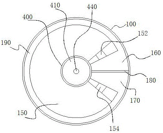
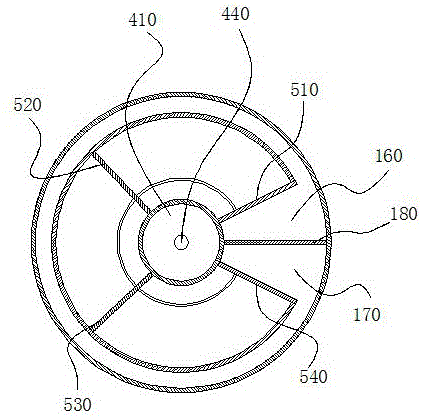
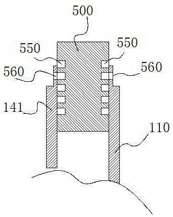
[0043] Such as Figure 1-5 As shown, the fermentation system includes a fermenter body 100, a gas storage plate 140 installed in the fermenter body 100, a hydraulic room 150 installed in the fermenter body 100, and a feed opening separating the fermenter body 100. plate 180, the fermenter body 100 is a ring structure, the fermenter body 100 includes the tank inner wall 110, the tank outer wall 120, the area between the tank inner wall 110 and the tank outer wall...


PUM


Abstract

The invention discloses a spiral type anaerobic fermentation system for making clean energy from plant straw. The system comprises a water pressure chamber on the top of a gas storage plate, and an auxiliary gas storage device connected with the gas storage plate. A bacteria distributing device is arranged on the water pressure chamber and comprises a plurality of bacteria distributing holes which are formed in the side wall, close to the flow disturbance area, of the water pressure chamber. The bacteria distributing holes are evenly distributed in the wall of the gas storage plate at intervals. The auxiliary gas storage device comprises an inner water pressure column body at the center of a fermentation tank body and an auxiliary gas storage plate installed in the inner water pressure column body and extending into a fermentation chamber. The auxiliary gas storage plate comprises an upper auxiliary plate, an inner vertical plate and an outer vertical plate. An opening of the auxiliary gas storage plate formed by the upper auxiliary plate, the inner vertical plate and the outer vertical plate faces downwards. The horizontal plane where the bottom of the inner vertical plate is located is higher than the horizontal plane where the bottom of a feed/discharge port gas baffle is located. The horizontal plane where the bottom of the outer vertical plate is located is lower than the horizontal plane where the bottom of the feed/discharge gas baffle is located.

Description

technical field [0001] The invention relates to the field of new energy and fermentation, in particular to a microbial fermentation treatment system for fermentation of raw materials such as straw and animal manure. Background technique [0002] The air ducts of the existing biogas fermentation systems are mostly poured with concrete and fixed on the top of the gas storage plate, and the airtightness of the surrounding is not high, and the air leakage around the surrounding is difficult to block; since the fermentation raw materials of the biogas digester are mostly livestock manure, manure During the decay process, various insects are easy to breed, and maggots crawl into the airway tube and cause blockage, which is difficult to clean; when there is water in the airway tube, it is difficult to discharge; the most prominent problem is that when the airway tube breaks, it is difficult to replace and can Lead to the scrapping of the whole biogas fermentation system. [0003] ...

Claims


Application Information

Patent Timeline
Patent Type & Authority Applications(China)
IPC IPC(8): C12M1/107C12M1/02C12P5/02C02F11/04
CPCC12M21/04C12M23/34C12M23/36C12M27/02C12M27/06C12M37/04C12P5/023Y02E50/30
Inventor 李俊
Owner 李俊
Why Eureka
Try Eureka