Construction method for filling dissolving cavity in outer side of deep foundation pit in karst area

A construction method and technology of deep foundation pits, applied in infrastructure engineering, construction, etc., can solve problems such as poor water sealing effect, achieve the effect of less investment, simple technical process, and small construction impact

Inactive Publication Date: 2016-08-24
CHINA RAILWAY CONSTR BRIDGE ENG BUREAU GRP NO 4 ENG
View PDF3 Cites 5 Cited by
  • Summary
  • Abstract
  • Description
  • Claims
  • Application Information

AI Technical Summary

Problems solved by technology

[0004] The invention aims to solve the problem of poor water-stopping effect in the deep foundation pit in the existing deep foundation pit excavation process in the existing karst area, and further provides a method for filling the outer solution cavity of the deep foundation pit in the karst area

Method used


Image

  • Construction method for filling dissolving cavity in outer side of deep foundation pit in karst area
  • Construction method for filling dissolving cavity in outer side of deep foundation pit in karst area
  • Construction method for filling dissolving cavity in outer side of deep foundation pit in karst area

Examples


specific Embodiment approach 1

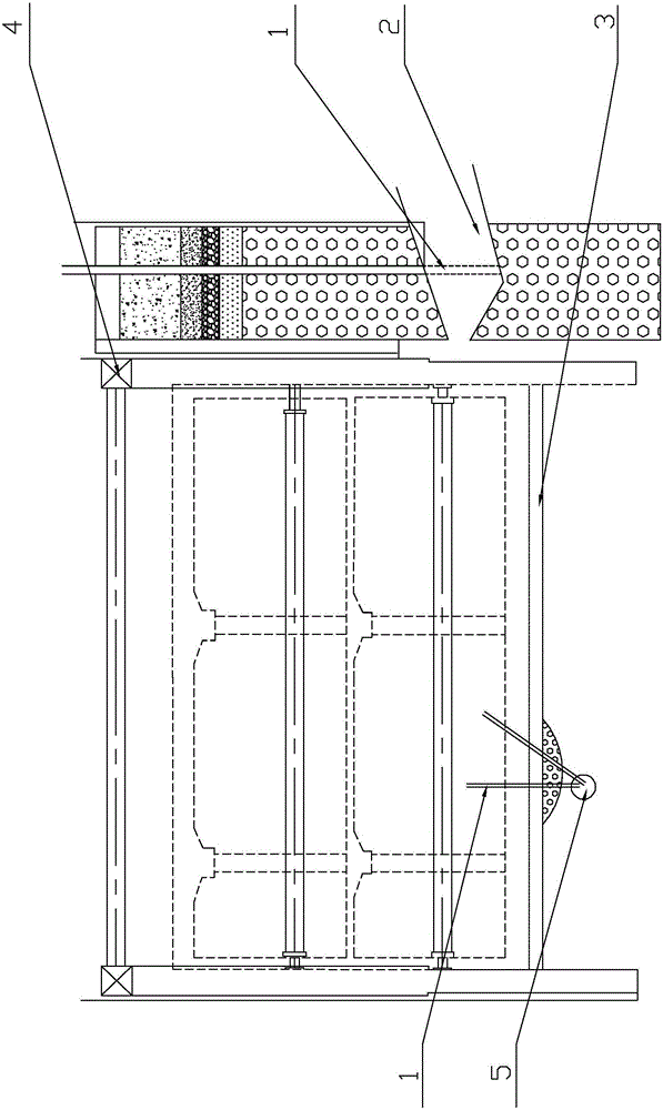
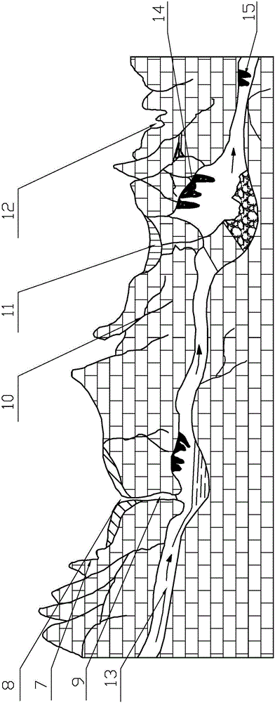
[0025] Specific implementation mode one: combine figure 1 and figure 2 Describe this embodiment, the method for filling the solution cavity outside the deep foundation pit in the karst area of ​​this embodiment, the steps of the construction method are as follows:

[0026] Step 1: Preliminary judgment of the location of the dissolution cavity

[0027] Check the geological survey data, the drilling data of the retaining piles, and combine the water gushing conditions in the deep foundation pit to preliminarily determine the location range and depth range of the dissolution cavity (for example, the 5-7m range is displayed as the dissolution cavity in the drilling record table, check the geological survey There are also dissolved cavities in the range of 5-7m from the data, and the leaking position of the foundation pit happens to be within the depth of 5-7m, so it can be preliminarily determined that there is a dissolved cavity in this position.);

[0028] Step 2: Use DTH Dri...

specific Embodiment approach 2

[0037] Specific implementation mode two: combination figure 2 To illustrate this embodiment, in step 3, the diameter of the lead hole drilled by the geological drill is 100mm. Designed so that it is easy to insert the grouting pipe. Other compositions and connections are the same as those in the first embodiment.

specific Embodiment approach 3

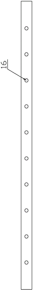
[0038] Specific implementation mode three: combination figure 2 To illustrate this embodiment, the floral tube in step 4 is made of iron pipe with a micro-pile material diameter of 42 mm and a wall thickness of 4 mm, and grout holes with a diameter of 10 mm are reserved every 500 mm on both sides of the tube axis. Such a design prevents the slurry hole from being blocked by the slurry in the dissolution cavity, and the slurry cannot be injected. Other compositions and connections are the same as those in Embodiment 1 or Embodiment 2.


PUM


Abstract

The invention provides a construction method for filling a dissolving cavity in the outer side of a deep foundation pit in a karst area and relates to a construction method in the technical field of building engineering. By the adoption of the construction method for filling the dissolving cavity in the outer side of the deep foundation pit in the karst area, the problem that in the prior art, the waterstop effect in the deep foundation pit is poor in the excavation process of the deep foundation pit in the karst area is solved. The construction method comprises the following steps that the position of the dissolving cavity is judged; a test hole is drilled by means of a down hole; drilling is conducted; a grouting pipe is inserted into the test hole; and grouting is conducted. A grouting pump is used for grouting, thin grout is made to pass through the hole firstly during grouting, dense grout starts to be injected after all the thin grout penetrate through a pipeline, and the grouting pressure is controlled to be 0.3-0.5 MPa; when continuous dense grout starts to appear in a water leakage position in the deep foundation pit, grouting continues to be conducted for 10-15 s and then is stopped; and grouting is started again after the grout in the dissolving cavity is solidified preliminarily till no grout or water gushes out from the water leakage position in the deep foundation pit. The construction method is used for reinforcement and water stop of the interior of the dissolving cavity.

Description

technical field [0001] The invention relates to a construction method in the technical field of construction engineering, in particular to a construction method for filling a dissolved cavity outside a deep foundation pit in a karst area. Background technique [0002] The Ministry of Construction's Jianzhi No. 200987 document on printing and distributing the "Notice on the Safety Management Measures for Sub-projects with Greater Risks" stipulates that general deep foundation pits refer to excavation depths exceeding 5 meters (including 5 meters) or basements with more than three floors ( including three floors), or projects whose depth is less than 5 meters but whose geological conditions, surrounding environment and underground pipelines are particularly complicated. During the excavation of deep foundation pits in karst areas, due to the fact that it is located in karst areas and the groundwater is abundant, as the excavation depth of foundation pits increases, the pressur...

Claims


Application Information

Patent Timeline
Patent Type & Authority Applications(China)
IPC IPC(8): E02D19/16
CPCE02D19/16
Inventor 刘洪双曲春国胡永福
Owner CHINA RAILWAY CONSTR BRIDGE ENG BUREAU GRP NO 4 ENG
Why Eureka
Try Eureka