A method of moving and strengthening steel pipe joints on grooved ring mouth plate

A technology of ring plate and groove type, which is applied in the direction of building maintenance, construction, building construction, etc., can solve the problems of brittle cracking of reinforced joints, difficult plate reinforcement, damage, etc., so as to improve the seismic ductility performance, avoid brittle damage, The effect of improving the static strength

Inactive Publication Date: 2018-07-27
CHINA UNIV OF MINING & TECH
View PDF10 Cites 0 Cited by
  • Summary
  • Abstract
  • Description
  • Claims
  • Application Information

AI Technical Summary

Problems solved by technology

However, when the width of the branch pipe is not much different from that of the main pipe, since there is no space for welding the board on the surface of the main pipe, it is not easy to achieve board reinforcement
Although the ring-wrap angle-wrapped plate method overcomes the limitation of the surface width of the main pipe and can be used to strengthen the joints of existing structures or new structures, the protection effect on weld cracking under tension needs to be improved, and the reinforced joints still have brittle cracks. sabotage risk

Method used


Image

  • A method of moving and strengthening steel pipe joints on grooved ring mouth plate
  • A method of moving and strengthening steel pipe joints on grooved ring mouth plate
  • A method of moving and strengthening steel pipe joints on grooved ring mouth plate

Examples


Embodiment Construction

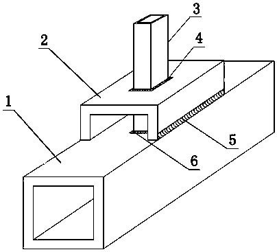
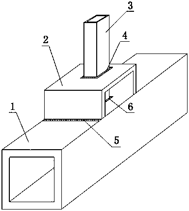
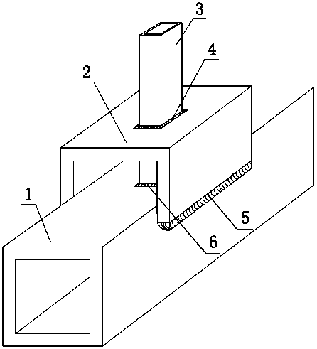
[0019] Option one: in figure 1 , 2 In 3, a method for moving a reinforced steel pipe node on a grooved ring plate, including: a reinforced node supervisor 1, a grooved ring plate 2, a branch pipe 3, a surrounding weld 4, a bilateral connection weld 5, and a central connection Weld seam 6; a branch pipe 3 is vertically welded in the middle of the top surface of the reinforced node main pipe 1; a grooved ring plate 2 is welded on the body of the branch pipe 3, and the grooved ring plate 2 is along the axis of the main pipe or perpendicular to Welding in the axial direction of the main pipe is on both sides of the main pipe 1 of the reinforced node or on the upper surface of the main pipe 1 of the reinforced node, thereby forming a surrounding weld 4, a central connection weld 6 and a bilateral connection weld 5; when the groove type When the annular plate 2 is arranged along the axial direction of the main tube 1 of the reinforced node, and the surface width of the main tube 1 ...


PUM


Abstract

The invention provides a method for reinforcing steel pipe joints by upward movement of a groove-shaped collar plate. A branch pipe is perpendicularly welded at the middle position of the top surface of a main pipe with the reinforced joints; the groove-shaped collar plate is welded on a pipe body of the branch pipe in a sleeving manner and is welded on two sides of the main pipe with the reinforced joints in the direction of the axis of the main pipe or in the direction perpendicular to the axis of the main pipe or welded on the upper surface of the main pipe with the reinforced joints, so that a surrounding welded joint, a center connecting welded joint and a double-side connecting welded joint are formed; and when the groove-shaped collar plate is arranged in the direction of the axis of the main pipe with the reinforced joints and the width of the surface of the main pipe with the reinforced joints difficultly guarantees welding of the double-side connecting welded joint, a flange of the groove-shaped collar plate can be welded with the side wall of the main pipe with the reinforced joints. The method for reinforcing the steel pipe joints by upward movement of the groove-shaped collar plate is not only suitable for reinforcement, repairing and strengthening of the steel pipe joints during service period, but also is suitable for machining the reinforced joints of steel pipe structures in the design stage. In the method, the collar plate and the welded joints of the branch pipe move upwards, the static strength of the joints can be improved, the welded joints of the main pipe and the branch pipe can be protected, brittle failure of the welded joints is avoided, and therefore, the anti-seismic ductility performance of the welding joints is improved.

Description

technical field [0001] The invention relates to a method for strengthening a steel pipe node, which belongs to the technical field of construction engineering, in particular to a method for moving and strengthening a steel pipe node on a groove-shaped annular plate. Background technique [0002] Steel pipe structures are widely used in buildings, bridges, towers, and offshore platform structures. Reliable node bearing capacity is very important to ensure structural safety. For hollow, thin-walled steel pipes, the radial stiffness is much smaller than the axial stiffness, and the radial bearing capacity at the nodes is much smaller than the axial bearing capacity. Therefore, the welding part of the joint is the most likely to be deformed or damaged in engineering practice, and the research on the reinforcement method of the joint is of great practical significance. The reinforcement methods of steel pipe joints can be divided into internal reinforcement methods and external ...

Claims


Application Information

Patent Timeline
Patent Type & Authority Patents(China)
IPC IPC(8): E04G23/02E04B1/58E04B1/24
CPCE04B1/2403E04B1/5831E04B2001/2406E04G23/02
Inventor 常鸿飞夏军武罗梓陈晓淼苏琼徐博周春波
Owner CHINA UNIV OF MINING & TECH
Why Eureka
Try Eureka