Supercharge Your Innovation With Domain-Expert AI Agents!

A wave device and a wave power generation device

A wave and sliding surface technology, applied in the field of fluid machinery, can solve the problem of low conversion efficiency and achieve the effect of improving workability

Inactive Publication Date: 2017-11-14
UNIV OF SHANGHAI FOR SCI & TECH
View PDF5 Cites 0 Cited by
  • Summary
  • Abstract
  • Description
  • Claims
  • Application Information

AI Technical Summary

Problems solved by technology

[0005] For the utilization of wind energy and water flow energy, the traditional method is to use the fluid with incoming velocity to generate the circulation around the blades to generate lift to do work on the blades. This method requires a large initial load to be applied to the blades to sustain energy. conversion, and the current use of lift to do work conversion efficiency is not high

Method used


Image

  • A wave device and a wave power generation device
  • A wave device and a wave power generation device
  • A wave device and a wave power generation device

Examples


Embodiment

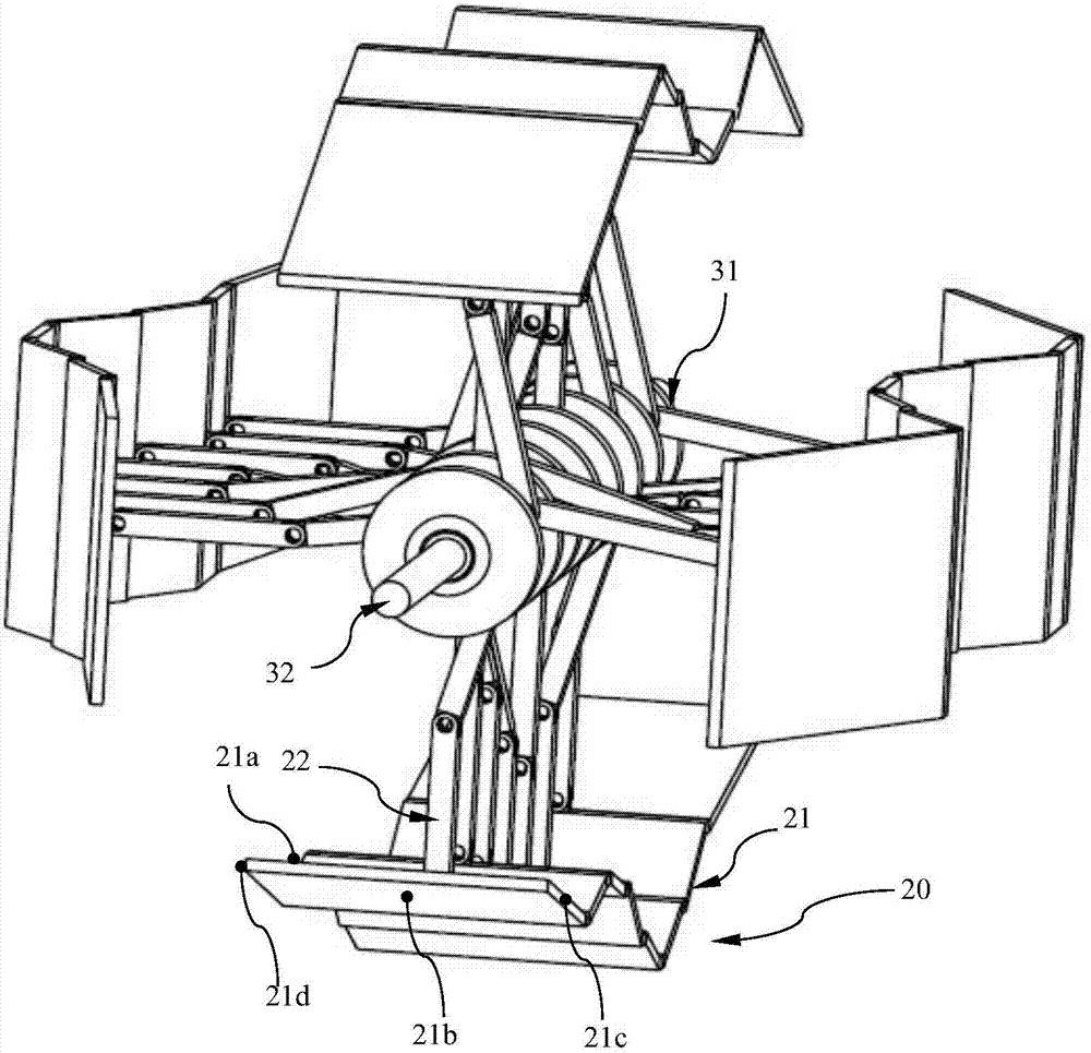
[0045] figure 1 This is a schematic structural diagram of the wave power generation device of this embodiment.

[0046] Such as figure 1 As shown, the wave power generation device 1000 includes a wave device 100 and a generator 200 (not shown in the figure). The wave device 100 transmits mechanical energy to the generator 200 through an output shaft and drives the generator 200 to run to generate electrical energy.

[0047] The wave device 100 includes a housing unit 10, four wave plate units 20 provided in the housing unit 10, and a crankshaft unit 30.

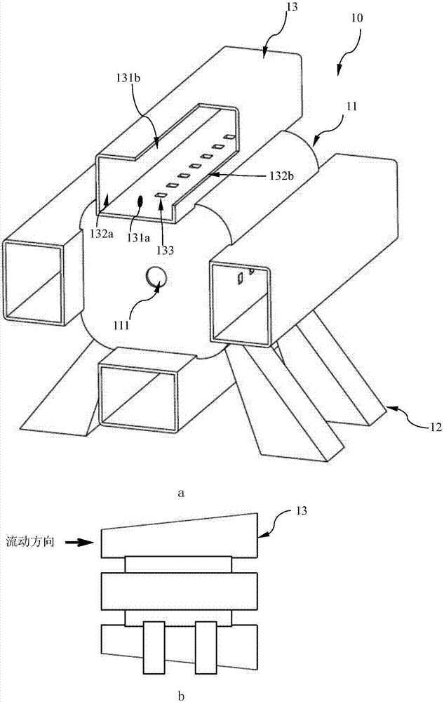
[0048] figure 2 It is a schematic diagram of the structure of the housing unit of the wave device of this embodiment, a is a schematic diagram of an isometric view, and b is a schematic diagram of a side view.

[0049] Such as figure 2 As shown, the housing unit 10 includes a cuboid-shaped housing 11, a load-bearing support composed of four load-bearing support columns 12, and four flow channels 13 arranged on the four side walls of...


PUM


Abstract

A fluctuation device is used for converting the flowing kinetic energy of gaseous or liquid working media into mechanical energy, and is characterized by comprising a shell unit, four fluctuation plate units and a crankshaft unit; the shell unit comprises a cuboid-shaped shell, a load bearing supporting part and four runners arranged on four side walls of the shell in parallel; the four fluctuation plate units are arranged in the four runners correspondingly; each fluctuation plate unit comprises a plurality of fluctuation plates and a plurality of equal-length connecting rods correspondingly and movably connected; the crankshaft unit is arranged in the shell and comprises a crankshaft mechanism and an output shaft which is connected to one end of the crankshaft mechanism and extends out of the shell. The working media flow through the four runners to drive the fluctuation plate units to fluctuate, the vertical fluctuation movement is transmitted to the crankshaft unit through the equal-length connecting rods along with fluctuation of the fluctuation plates, and the crankshaft unit converts the vertical fluctuation movement into rotation movement which is output through the output shaft. The fluctuation device can convert the kinetic energy of the fluid in the fluctuation form into the mechanical energy, and is stable in work and high in efficiency.

Description

Technical field [0001] The invention relates to the field of fluid machinery, in particular to a wave device that converts the generalized thermal energy of a fluid into mechanical energy output in one direction. Background technique [0002] There are generally two types of devices that convert the generalized internal energy of a fluid into mechanical work. One is the piston-type crank connecting rod power device that uses the thermal expansion of the fluid to generate pressure to push the piston to reciprocate. The other is the expansion of the hot fluid through the nozzle to reduce the enthalpy. The impeller mechanical power device that is converted into kinetic energy to drive the impeller to rotate. [0003] The shape and characteristics of the piston-type crank connecting rod power unit are suitable for thermal conversion occasions with a closed air chamber with a large compression ratio. It has high efficiency, small size and light weight, and a large stable working range. ...

Claims


Application Information

Patent Timeline
Patent Type & Authority Patents(China)
IPC IPC(8): F03C4/00F03D5/06F03D9/25F01C9/00
CPCF01C9/00F03C4/00F03D5/06Y02E10/70
Inventor 韩玮白音祜汪鹏军黄典贵
Owner UNIV OF SHANGHAI FOR SCI & TECH
Features
  • R&D
  • Intellectual Property
  • Life Sciences
  • Materials
  • Tech Scout
  • Unparalleled Data Quality
  • Higher Quality Content
  • 60% Fewer Hallucinations
Learn More