
Coaxial multi-stage gearbox

A gearbox, coaxial technology, applied in the direction of transmission boxes, gear transmissions, components with teeth, etc., can solve the problems of low deceleration efficiency, inconvenient, limited, etc., and achieve the effect of improving service life and reducing loss

Inactive Publication Date: 2016-08-24
ZHEJIANG HUIXIN DRIVING MACHINE
View PDF9 Cites 1 Cited by
  • Summary
  • Abstract
  • Description
  • Claims
  • Application Information

AI Technical Summary

Problems solved by technology

[0004] However, the transmission of the traditional reducer with variable speed function is relatively small, resulting in low deceleration efficiency, and the scope of application is relatively single and limited. It still cannot meet many work requirements, resulting in certain limitations and inconvenience.

Method used


Image

  • Coaxial multi-stage gearbox
  • Coaxial multi-stage gearbox
  • Coaxial multi-stage gearbox

Examples


Embodiment Construction

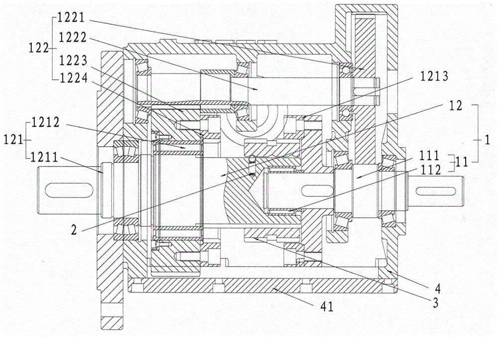
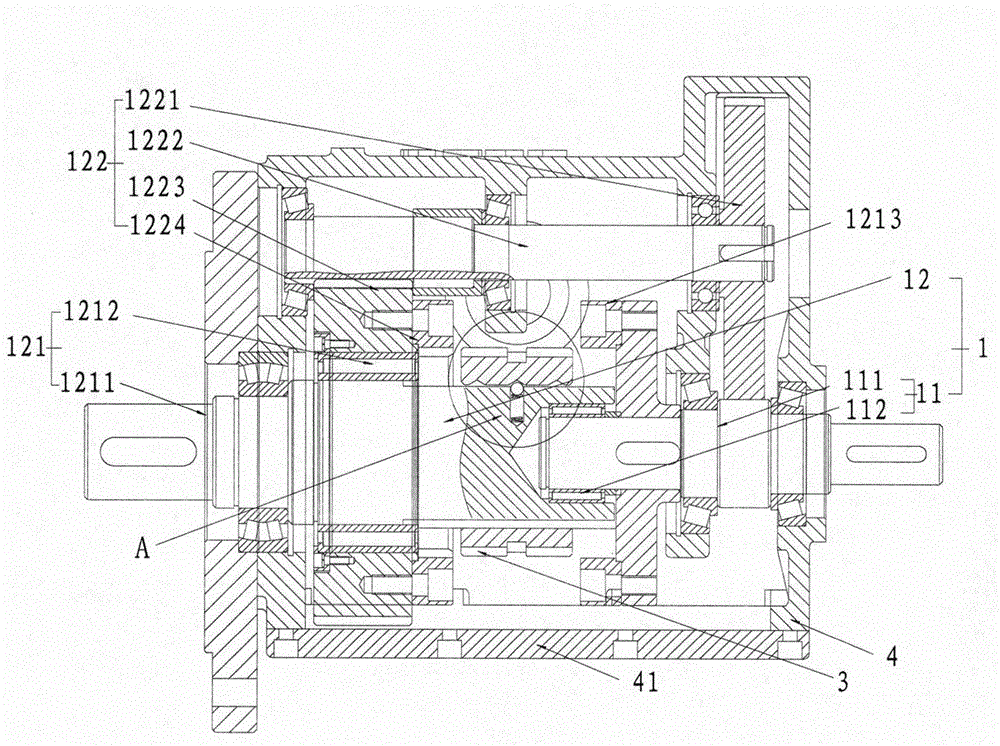
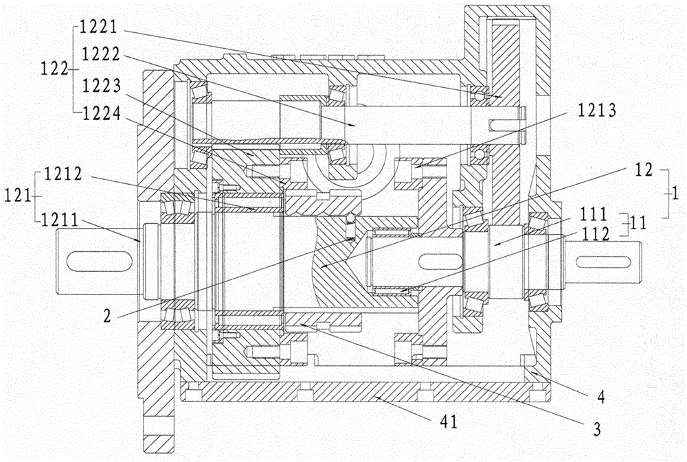
[0030] refer to Figure 1 to Figure 5 The embodiment of the coaxial multi-stage gearbox of the present invention will be further described.

[0031] A coaxial multi-stage gearbox includes a box body 4, and the box body 4 is provided with a driving device 1 and an adjusting transmission device 3 that can be engaged with the driving device 1 so that the driving device 1 outputs various powers.

[0032] The driving device 1 includes an input system 11, the input system 11 includes an input drive pinion 111; and an output system 12, the output system 12 includes an output main shaft 1212, which can be engaged with the input drive pinion 111 to output various powers. The driving output device 121 and the driven output device 122 ; the adjusting transmission device 3 includes a clutch gear meshed with the driving output device 121 and the driven output device 122 , and the output main shaft 1212 runs through the clutch gear.

[0033] The box body 4 includes a first housing 41; the ...


PUM


Abstract

The invention discloses a coaxial multi-stage gearbox. The coaxial multi-stage gearbox comprises a box body, wherein a driving device and a speed changing adjusting device are arranged in the box body; the speed changing adjusting device can be engaged with the driving device so that the driving device outputs various powers; the driving device comprises an input system and an output system; the input system comprises an input driving gear shaft; the output system comprises an output spindle which can be engaged with the input driving gear shaft and outputs power; the speed changing adjusting device comprises a clutch gear; and the output spindle penetrates through the clutch gear. The box body comprises a first shell; the output system comprises a driving output device and a driven output device; the driving output device comprises an output spindle and a first clutch inner gear ring which is fixedly arranged on a reverse side, which is opposite to the first shell, of the clutch gear; and the driven output device comprises a second clutch inner gear ring. The coaxial multi-stage gearbox has the advantages that a speed changing range is large, retardation efficiency is high, various powers can be output, speed changing in various grades is realized, and an infinite step speed changing range can be obtained.

Description

technical field [0001] The invention relates to a mechanical device, in particular to a speed reducer. Background technique [0002] The traditional reducer is delivered at a constant speed, while the gearbox can change the transmission ratio, rotation direction (such as reverse gear) and set neutral gear of the reducer. There are many structures and principles. For example, automobile gearboxes are divided into manual and automatic, and also divided into gear type and electric type. [0003] The transmission ratio is the ratio of the angular velocity of the two rotating components in the mechanism, also known as the speed ratio, which is equal to the ratio of the input shaft speed to the output shaft speed, that is, equal to the product ratio of all driven gear teeth to the product of all driving gear teeth. [0004] However, the transmission of the traditional reducer with variable speed function is relatively small, resulting in low reduction efficiency, and the scope of...

Claims


Application Information

Patent Timeline
Patent Type & Authority Applications(China)
IPC IPC(8): F16H57/02F16H3/091
Inventor 应成龙
Owner ZHEJIANG HUIXIN DRIVING MACHINE
Learn More