
Power transmission conductor galloping amplitude measurement method

A technology of power transmission wires and measurement methods, which is applied to measuring devices, measuring ultrasonic/sonic/infrasonic waves, instruments, etc., can solve the problems of limited observation angle, large calculation error of galloping amplitude, and dependence on observation points that personnel can reach, etc. Accurate results, quick installation, and compensation for limited measurement angles

Inactive Publication Date: 2016-08-24
ELECTRIC POWER RES INST STATE GRID JIANGXI ELECTRIC POWER CO +1
View PDF5 Cites 2 Cited by
  • Summary
  • Abstract
  • Description
  • Claims
  • Application Information

AI Technical Summary

Problems solved by technology

Although the handheld device can effectively obtain the galloping form of any position of the conductor within the span, the galloping condition of the conductor depends on the observation point that personnel can reach, and the galloping observation of the conductor can only be performed on the ground. Due to the limited observation angle, galloping Amplitude calculation error is large

Method used


Image

  • Power transmission conductor galloping amplitude measurement method
  • Power transmission conductor galloping amplitude measurement method
  • Power transmission conductor galloping amplitude measurement method

Examples


Embodiment Construction

[0018] The present invention proposes a measurement method for the galloping amplitude of a transmission wire, and the invention will be further described in detail below in conjunction with the accompanying drawings and embodiments.

[0019] The on-site measurement method for the galloping amplitude of the transmission conductor proposed in this embodiment.

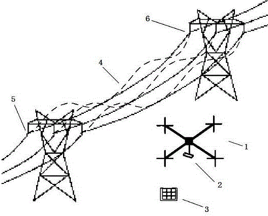
[0020] The embodiment of the present invention is realized by a measuring device for a small unmanned aerial vehicle. The measuring device of the small drone is composed of a small remote control drone 1 and a small high-definition camera 2 with a cross scale. The small high-definition camera 2 realizes multi-angle and all-round shooting of the dancing shape of the transmission wire, and then measures the dancing amplitude. value to measure.

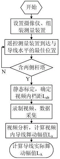
[0021] When using it, first set up the HD camera, fix the HD camera firmly to the bottom of the small remote control drone through its top bolt, and keep its lens level. During t...


PUM


Abstract

The invention relates to a power transmission conductor galloping amplitude measurement method. According to the power transmission conductor galloping amplitude measurement method, a measurement device composed of a small-sized remote control unmanned aerial vehicle (1) and a small-sized high-definition image pickup instrument (2) which has cross scale marks and is installed at the bottom of the small-sized remote control unmanned aerial vehicle (1) is utilized to realize multi-azimuth and multi-angle observation of the galloping form of a power transmission conductor (3). With the power transmission line galloping amplitude measurement method adopted, an optimal position can be selected, so that the galloping amplitude of the power transmission conductor can be measured at the position, and a measurement angle and the conductor are located at the same horizontal plane; the images of the highest point and the lowest point of the galloping of the conductor can be obtained accurately; a conversion method is simpler; the defects of limited measurement angles and complex conversions methods in existing methods can be eliminated; measurement results can be more accurate and effective; the measurement results can provide data support for follow-up galloping prevention and control work; and safe and stable operation of a power grid can be ensured.

Description

technical field [0001] The invention relates to a method for measuring the galloping amplitude of a transmission wire, which belongs to the technical field of transmission line wire measurement. Background technique [0002] A variety of disasters and accidents will occur due to natural conditions during the operation of overhead transmission lines, and galloping is one of the more serious hazards. Galloping is a self-excited vibration with low frequency (about 0.1-5 Hz) and large amplitude (about 20-300 times the diameter of the wire) produced by uneven ice-coated wires under the action of wind. There is only one or a few half-waves in a span. The occurrence of galloping in transmission lines usually depends on three factors: uneven icing of conductors, wind excitation and line structural parameters. The harm caused by galloping is multifaceted. The light ones will cause flashover and tripping. The severe ones will cause damage to hardware and insulators, broken strands a...

Claims


Application Information

Patent Timeline
Patent Type & Authority Applications(China)
IPC IPC(8): G01H9/00
CPCG01H9/00
Inventor 饶斌斌李阳林周龙武邹建章况燕军胡京
Owner ELECTRIC POWER RES INST STATE GRID JIANGXI ELECTRIC POWER CO
Learn More